
Wafer retaining system and semiconductor processing apparatus applying the system

A semiconductor and chip technology, applied in the field of microelectronics, can solve problems such as difficult control, reduced service life of components, increased cost, etc., and achieve the effects of increasing heat transfer effect, improving product yield, and improving temperature uniformity

Active Publication Date: 2009-07-22
BEIJING NAURA MICROELECTRONICS EQUIP CO LTD
View PDF1 Cites 11 Cited by
  • Summary
  • Abstract
  • Description
  • Claims
  • Application Information

AI Technical Summary

Problems solved by technology

[0011] Yet in actual application, there is such defective in above-mentioned dry cleaning technology: one, need to implement above-mentioned dry cleaning process additionally outside actual technological process, thus reduced the production efficiency of system; During the process, the oxygen introduced into the reaction chamber will not only react with the aforementioned polymer to remove it, but also attack the parts in the reaction chamber (for example, the upper surface of the more expensive electrostatic chuck will be damaged during the dry process). are exposed to oxygen attack during cleaning), thereby reducing the service life of these parts
However, in a typical electrostatic chuck system, the vertical gap between the focus ring and the wafer is small, and a step change in the height of the base ring will make the vertical gap between the focus ring and the wafer less controllable
[0016] Second, if the height of the base ring is to be adjusted in a small amount, it is necessary to set the variation of the step height of the stationary ring to be small, which will make processing difficult and lead to an increase in cost

Method used


Image

  • Wafer retaining system and semiconductor processing apparatus applying the system
  • Wafer retaining system and semiconductor processing apparatus applying the system
  • Wafer retaining system and semiconductor processing apparatus applying the system

Examples


Embodiment Construction

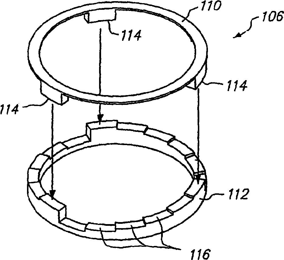
[0043] In order to enable those skilled in the art to better understand the technical solution of the present invention, the wafer clamping system provided by the present invention and the semiconductor processing equipment using the clamping system will be described in detail below with reference to the accompanying drawings.

[0044] The wafer clamping system provided by the present invention may include: a clamping tool such as an electrostatic chuck; a movable base ring disposed around the clamping tool; a focus ring placed on the movable base ring, and is also arranged around the clamping tool; and a lifting adjustment assembly, which includes a first adjustment part and a second adjustment part, and the first adjustment part and the second adjustment part cooperate with each other so that the movable base ring is relatively The clamping tool can be continuously lifted to drive the focus ring on the movable base ring to continuously lift, so that the distance between the u...


PUM


Abstract

The invention discloses a crystal clamping device which is applied to fixing a semiconductor device to be processed / disposed in the process of semiconductor processing / disposing, comprising a clamping tool, a movable basic ring arranged around the clamping tool and a focusing ring arranged above the movable basic ring and around the clamping tool. The crystal clamping tool is further provided with a lifting regulating component composed of a first regulating part and a second regulating part, the first regulating part and the second regulating part coordinate with each other, so that the movable basic ring can continuously move upwards and downwards relative to the clamping tool to drive the focusing ring to continuously move upwards and downwards, as a result, the distance between the upper surface of the focusing ring and the upper surface of the clamping tool can be continuously adjusted. In addition, the invention also provides a semiconductor processing device applied to the crystal clamping system. The crystal clamping system and the semiconductor processing device of the invention can carry out continuous and accurate adjustment of the distance between the upper surface of the focusing ring and the upper surface of the clamping tool, thus improving product yield, moreover, the invention facilitates processing.

Description

technical field [0001] The present invention relates to the technical field of microelectronics, and more particularly, to a wafer clamping system for semiconductor processing / handling process. In addition, the present invention also relates to a semiconductor processing equipment using the wafer clamping system. Background technique [0002] In the integrated circuit (IC) manufacturing process, especially in the plasma etching (ETCH), physical vapor deposition (PVD), chemical vapor deposition (CVD) and other processes, in order to fix, support and transfer the wafer (Wafer) etc. To process the device, to avoid movement or dislocation of the processed device, a wafer clamping device such as an Electro Static Chuck (ESC for short) or a mechanical clamp is often used. [0003] Among them, electrostatic chucks use electrostatic attraction to fix processed devices such as wafers, which can be divided into two types: Coulomb and Johnson-Rahbek. Since the electrostatic chuck use...

Claims


Application Information

Patent Timeline
Patent Type & Authority Applications(China)
IPC IPC(8): H01L21/683H01L21/67H01L21/00C23C16/458C23C14/50C30B25/12H01J37/32H05H1/24
Inventor 张小昂
Owner BEIJING NAURA MICROELECTRONICS EQUIP CO LTD
Learn More