Conveying apparatus using slide loading platform

A technology for handling devices and platforms, applied in transportation, packaging, motor vehicles, etc., to achieve the effect of good straightness and restraint of wear

Active Publication Date: 2009-07-22
DAIFUKU CO LTD
View PDF2 Cites 4 Cited by
  • Summary
  • Abstract
  • Description
  • Claims
  • Application Information

AI Technical Summary

Problems solved by technology

Although this kind of conveying device using a sliding stage is an invention that can be easily imagined by those in this technical field, in the prior art, there is no specific and practical structure in a conveying device utilizing this sliding stage

Method used


Image

  • Conveying apparatus using slide loading platform
  • Conveying apparatus using slide loading platform
  • Conveying apparatus using slide loading platform

Examples


Embodiment Construction

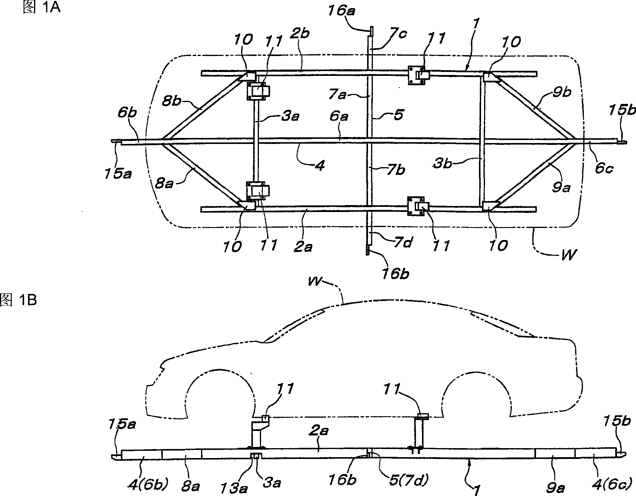
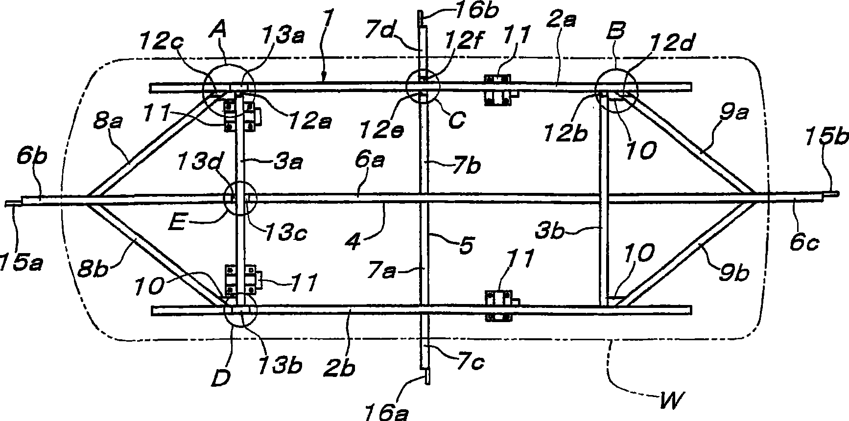
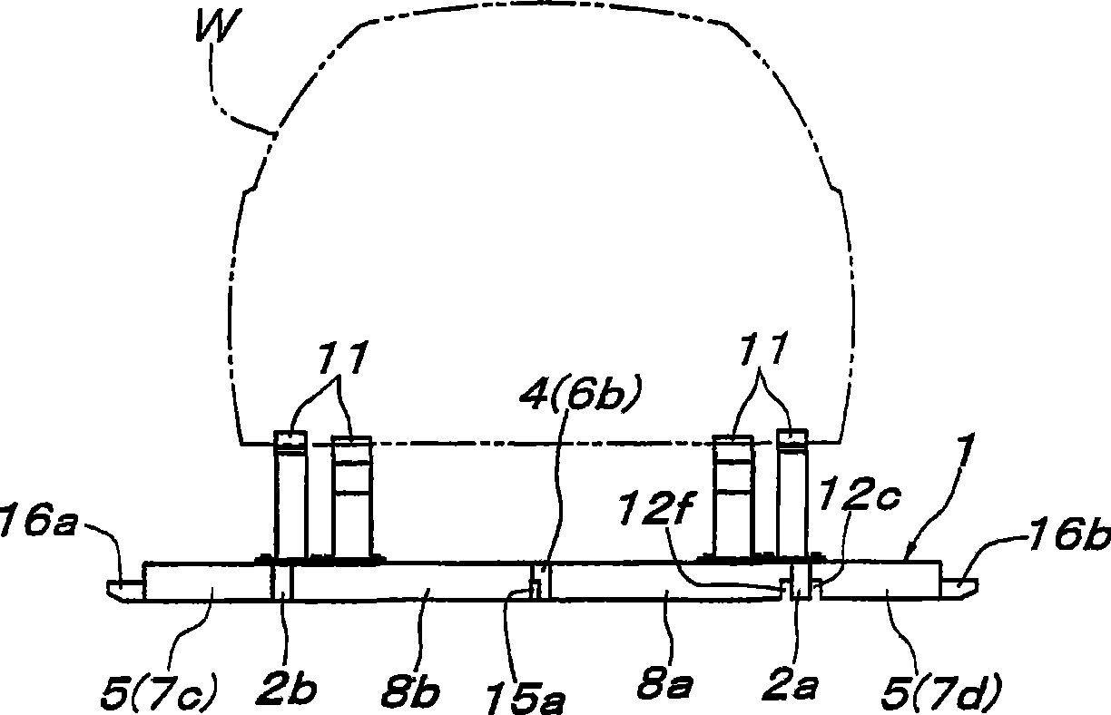
[0079] Although the specific embodiments of the present invention are described below according to the drawings, in Fig. 1A, Fig. 1B, Figure 1C and figure 2 Among them, 1 is a sliding stage supporting the workpiece (automobile body) W, including a pair of left and right long rod-shaped sliding members 2a, 2b parallel to the longitudinal direction of the supported workpiece W, and the width direction of the supported workpiece W A pair of parallel front and rear short rod-shaped sliding members 3a, 3b are arranged at the center between the long rod-shaped sliding members 2a, 2b parallel to the longitudinal direction of the supported workpiece W and is longer than the total length of the supported workpiece W A long longitudinal feed rod 4 for friction drive and a short rod-shaped sliding member 3a, 3b arranged in the center position parallel to the width direction of the supported workpiece W and longer than the width of the supported workpiece W A friction drive rod 4 for horizo...


PUM


Abstract

The invention discloses a conveyer apparatus using a sliding carrier, which makes setting operation of friction driven conveyer apparatus without sliding state of wheel capable of being simplified. Divided into length for individually supporting the sliding carrier comprising friction driven rods, guide rail units disconnected with each other and independently disposed are configured on the driving path of the sliding carrier. Each guide rail unit comprises a pair of left and right roller guide rail for movably supporting a pair of left and right rod shaped sliding means, an integrated connection means formed by connecting two roller guide rails, and a friction driver installed onto the connection means and disposed on one end of the longitudinal direction of the guide rail unit. Each guide rail unit is set in a manner that intervals between driver roller of friction driver thereof is substantially equal to the storage pitch L1 of the sliding carrier under the state that friction driver rods alternately engage with each other.

Description

Technical field [0001] The present invention relates to a conveying device using a sliding carrier that slides on a roller guide rail on the side of a walking path. Background technique [0002] A conveying device that pushes a carrier by a drive roller of a friction drive on the traveling path side is disclosed in Patent Document 1 and the like. On the other hand, it is also disclosed in Patent Document 2 and the like that the carrier is movably supported by roller guides on the side of the traveling path without providing wheels on the stage. Therefore, the stage described in Patent Document 1 is supported by the method described in Patent Document 2, whereby a sliding stage supported movably on the roller guide laid on the side of the traveling path is provided with The friction drive rods with parallel directions are pressed against the drive rollers of the friction drive provided on the traveling path side via the friction drive rods on the stage side to push the sliding sta...

Claims


Application Information

Patent Timeline
IPC IPC(8): B62D65/18
Inventor 西原重善铃木孝晴
Owner DAIFUKU CO LTD
Why Eureka
Try Eureka