
Clutch brake component of punch press

A technology for brakes and components, applied in the direction of presses, manufacturing tools, etc., can solve the problems of poor practicability and pollution of the working environment, and achieve the effect of strong practicability, improving working environment and upgrading grades

Active Publication Date: 2011-10-12
XIANGSHAN YIDUAN PRECISION MACHINERY CO LTD
View PDF6 Cites 0 Cited by
  • Summary
  • Abstract
  • Description
  • Claims
  • Application Information

AI Technical Summary

Problems solved by technology

This structure combines the original two distributed clutches and brakes into a centralized installation of the clutch and brake components. It has a compact structure and a small volume, and can effectively control the fast combination and fast braking of the punching machine. The braking performance is good and the production efficiency is improved. The working energy of the punching machine is fixed and cannot be changed, the practicability is not strong, and it cannot meet the needs of customers well, and the dust and noise that the clutch brake is easy to produce during work will cause certain pollution to the working environment

Method used


Image

  • Clutch brake component of punch press
  • Clutch brake component of punch press
  • Clutch brake component of punch press

Examples


Embodiment Construction

[0017] The present invention will be further described in detail below in conjunction with the embodiments of the accompanying drawings.

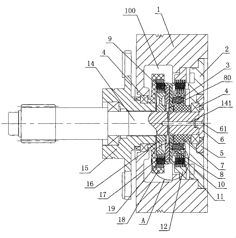
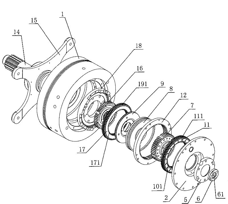
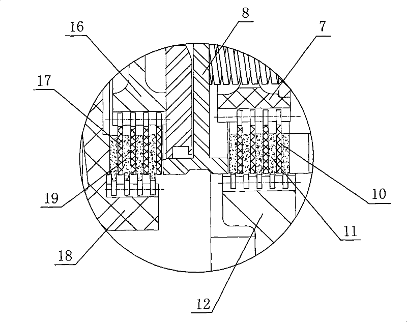
[0018] As shown in the figure, a clutch brake assembly of a punching machine includes a flywheel 1, a transmission shaft 14 and a flywheel shaft 15 that is pivotally connected to the transmission shaft 14, and the flywheel shaft 15 is connected to the punching machine body (not shown in the figure) by fixing screws. Shown) is fixedly connected, the flywheel 1 is connected to the flywheel shaft 15 through the sealed shaft of the bearing 4, the flywheel 1 is provided with an inner cavity 100, and the transmission shaft 14 is coaxially fixedly connected with the brake outer gear 16 and the clutch outer gear 7 through the heating and shrinking process , the brake outer teeth 16 and the clutch outer teeth 7 are arranged in the inner cavity 100, and the brake inner teeth 18 are coaxially fixedly connected to the flywheel shaft 15 through the heati...


PUM


Abstract

The invention discloses a clutch brake assembly for a punch press, which comprises a fly wheel, a driving shaft and a fly wheel bearing coupled on the driving shaft, and is characterized in that the driving shaft is coaxially and fixedly provided with brake outer teeth and clutch outer teeth; the fly wheel bearing is coaxially and fixedly provided with brake inner teeth; a brake friction assemblyis arranged between the brake inner teeth and the brake outer teeth; the fly wheel is fixedly provided with clutch inner teeth; a clutch friction assembly is arranged between the clutch inner teeth and the clutch outer teeth; the driving shaft is coaxially and air-tightly sleeved with an air cylinder; a piston is arranged in the air cylinder; an air chamber is arranged between the piston and the air cylinder; the driving shaft is provided with an air inlet communicated with the air chamber; and a spring is supported between the air cylinder and the clutch outer teeth. The clutch brake assembly has the advantages of satisfying different actual needs of the punch press in work, completely changing the mode that the operation capacity of the prior punch press is changeless, having strong practicability, effectively collecting dust consumed by a friction plate and reducing noise, and greatly promoting and improving the working environment for the punch press.

Description

technical field [0001] The invention relates to a component on mechanical processing equipment, in particular to a clutch brake component of a press. Background technique [0002] At present, the brake parts and clutch parts on the desktop punching machine are generally split, and are respectively installed on the front and rear ends of the frame. The rotation of the crankshaft is constantly in contact with the crank part of the crankshaft, so no matter whether the flywheel controlled by the clutch is driven or separated from the crankshaft, the brake belt is always in working condition, which increases the wear of the brake belt and increases the energy consumption. After use, the braking effect is not good, there is a potential safety hazard, and the work efficiency is not ideal. [0003] In order to solve the above-mentioned existing problems, the Chinese Utility Model Patent Application Specification with the application number 200820164052.2 discloses a clutch brake as...

Claims


Application Information

Patent Timeline
Patent Type & Authority Patents(China)
IPC IPC(8): B30B15/12
Inventor 王赛珍
Owner XIANGSHAN YIDUAN PRECISION MACHINERY CO LTD
Learn More