Power transmission control device, power transmitting device, non-contact power transmission system, electronic instrument, and power transmission control method
A technology of power transmission device and control device, applied in circuit devices, electromagnetic wave systems, battery circuit devices, etc., can solve problems such as abnormal heat generation and equipment damage, and achieve the effects of high convenience, restraint power consumption, and reduced number of components
- Summary
- Abstract
- Description
- Claims
- Application Information
AI Technical Summary
Problems solved by technology
Method used
Image
Examples
no. 1 approach
[0074] First, examples of preferable electronic equipment to which the present invention is applied and the principle of non-contact power transmission technology will be described.
[0075] (Example of electronic equipment and principle of non-contact power transmission)
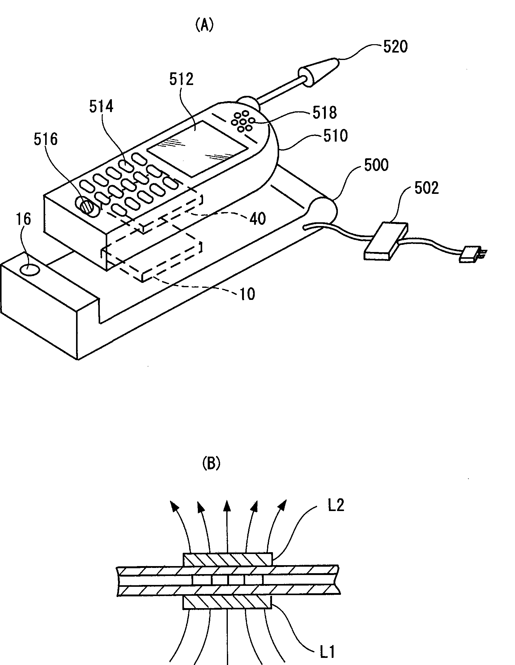
[0076] figure 1 (A) and figure 1 (B) is an explanatory diagram for explaining an example of electronic equipment to which the non-contact power transmission method is applied and the principle of non-contact power transmission using an induction transformer.
[0077] Such as figure 1 As shown in (A), a charger (cradle) 500 serving as a power transmission side electronic device includes a power transmission device (such as a power transmission module including a power transmission side control circuit (power transmission side control IC)) 10 . Furthermore, this charger (cradle) 500 includes a display unit (LED, etc.) 16 that lights up when the charger transmits power normally.
[0078]A mobile phone 510 ...
no. 2 approach
[0165] In this embodiment, detection of an encroachment state (encroachment heat generation countermeasure) will be specifically described. The "encroachment state" is defined as a special state in which a foreign object is inserted, and refers to "the state in which the foreign object is mistaken for the power receiving side equipment and the normal power transmission continues." For example, when a thin metal plate is inserted so as to completely cover the gap between the primary coil and the secondary coil, there will always be a considerable load when viewed from the power transmission side, making removal detection difficult, for example.
[0166] (Invasion fever countermeasures)
[0167] First, the "occupied state" will be specifically described. There may be a case where, for example, a large-area foreign object is inserted between the primary coil L1 and the secondary coil L2 after the authentication of the power receiving device (or power receiving side equipment) is...
no. 3 approach
[0231] In this embodiment, recharging after full charging will be described. After being fully charged, for example, if a mobile phone terminal as a device on the power receiving side is placed on a charging stand (cradle) for a long time, the voltage drops due to discharge of the battery, and the battery becomes a state requiring recharging. Therefore, in this embodiment, the power transmission device automatically detects the necessity of recharging after it is fully charged.
[0232] (recharge after full charge)
[0233] Figure 10 (A) and Figure 10 (B) is a timing chart showing a series of operation steps for managing recharging after full charge in the contactless power transmission system. in addition, Figure 10 The steps shown in (B) are in Figure 10 The step shown in (A) is followed.
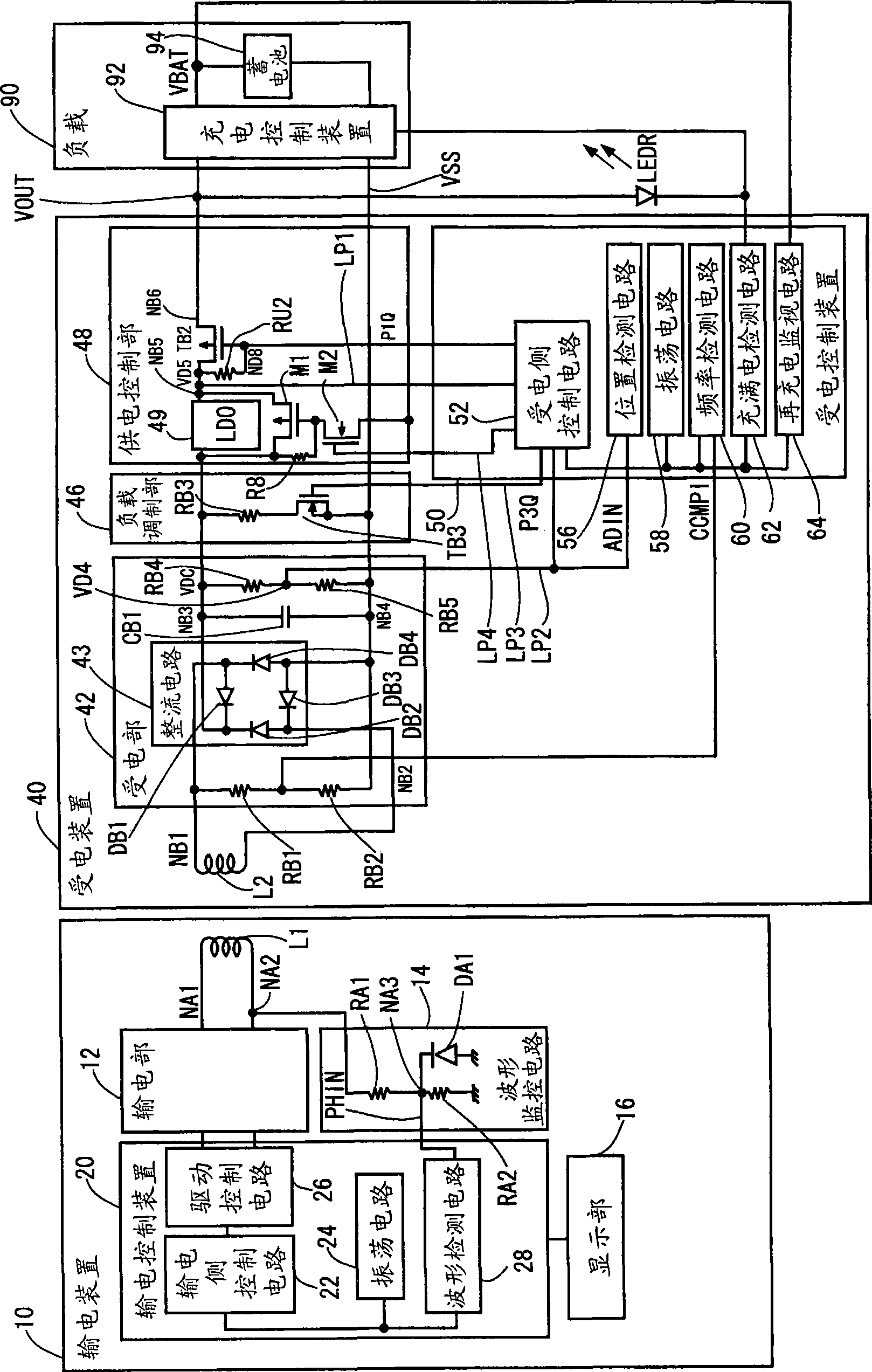
[0234] If the battery 94 (see figure 2 ) into a fully charged state, then switch to the fully charged standby mode. In this fully charged standby mode, the power transmission...
PUM
 Abstract
Description
Claims
Application Information
 - R&D
- Intellectual Property
- Life Sciences
- Materials
- Tech Scout
- Unparalleled Data Quality
- Higher Quality Content
- 60% Fewer Hallucinations
Browse by: Latest US Patents, China's latest patents, Technical Efficacy Thesaurus, Application Domain, Technology Topic, Popular Technical Reports.
© 2025 PatSnap. All rights reserved.Legal|Privacy policy|Modern Slavery Act Transparency Statement|Sitemap|About US| Contact US: help@patsnap.com


