Expansion positioning mechanism for satellite antenna

A positioning mechanism and space-borne antenna technology, applied in the mechanical field, can solve the problems of positioning mechanism position detection, damage deployment positioning mechanism, and short distance of hanging beams, etc., to reduce frictional resistance, improve safety, and avoid external collisions.

Active Publication Date: 2009-07-15
中国航天科技集团公司第五研究院第五〇四研究所
View PDF0 Cites 12 Cited by
  • Summary
  • Abstract
  • Description
  • Claims
  • Application Information

AI Technical Summary

Problems solved by technology

[0003] Since the original deployment and positioning mechanism is installed outside the antenna support structure, the tooling is easy to touch the deployment and positioning mechanism during the ground test and the antenna star installation process, causing the position of the positioning mechanism to be detected due to external force collisions, or the deployment and positioning mechanism is damaged. Based on this, Develop a new set of deployment positioning mechanism to improve product safety
The original deployment and positioning mechanism needs to complete the task together with the arc-shaped guide plate of the deployment arm at the rear of the antenna reflector. It can only be installed outside the antenna, protruding from the outside of the antenna. The position is close to the lifting beam of the whole star, and it is easy to operate. came across the agency

Method used


Image

  • Expansion positioning mechanism for satellite antenna
  • Expansion positioning mechanism for satellite antenna
  • Expansion positioning mechanism for satellite antenna

Examples


Embodiment Construction

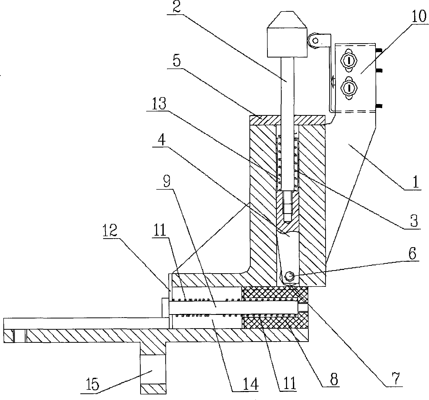
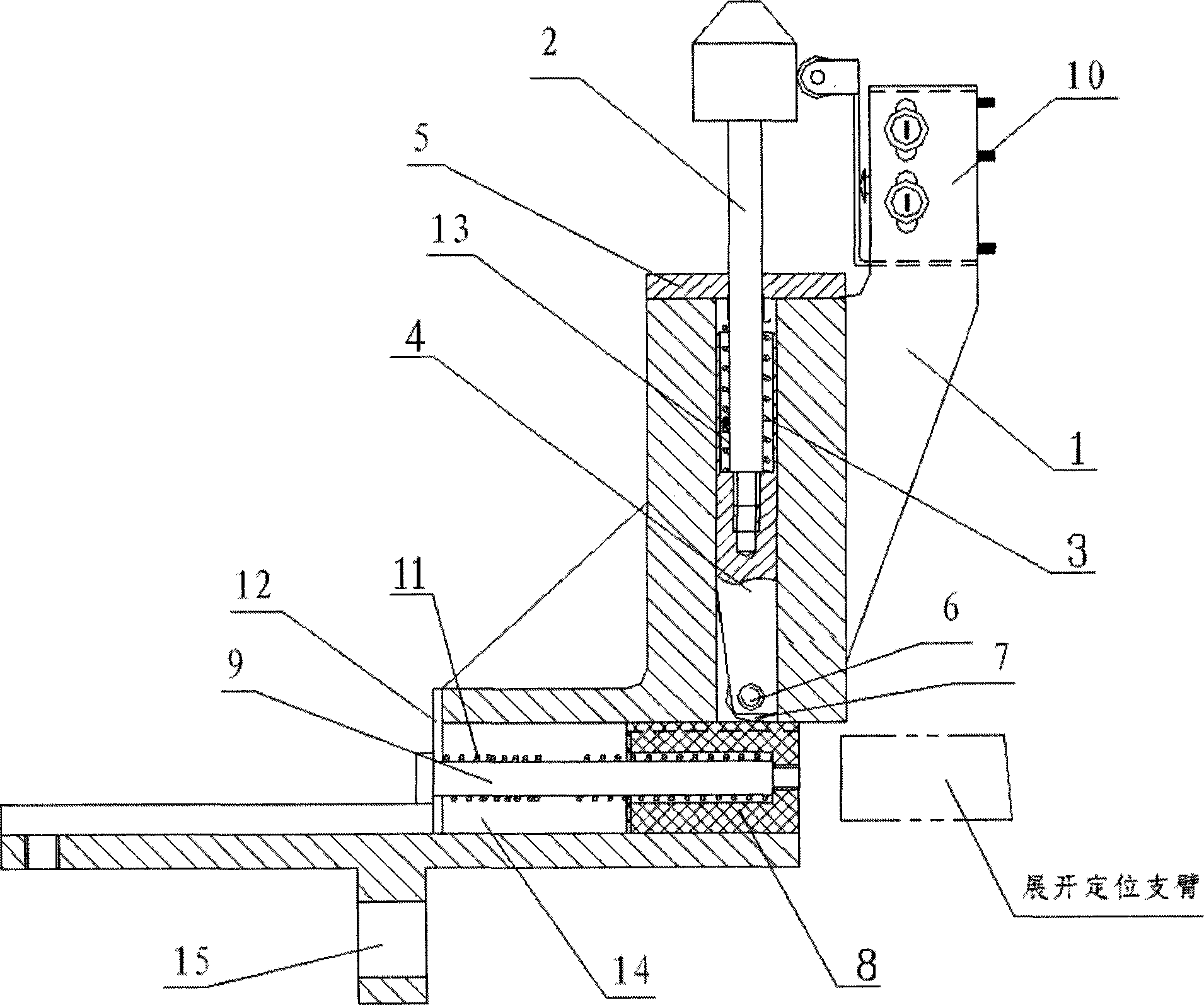
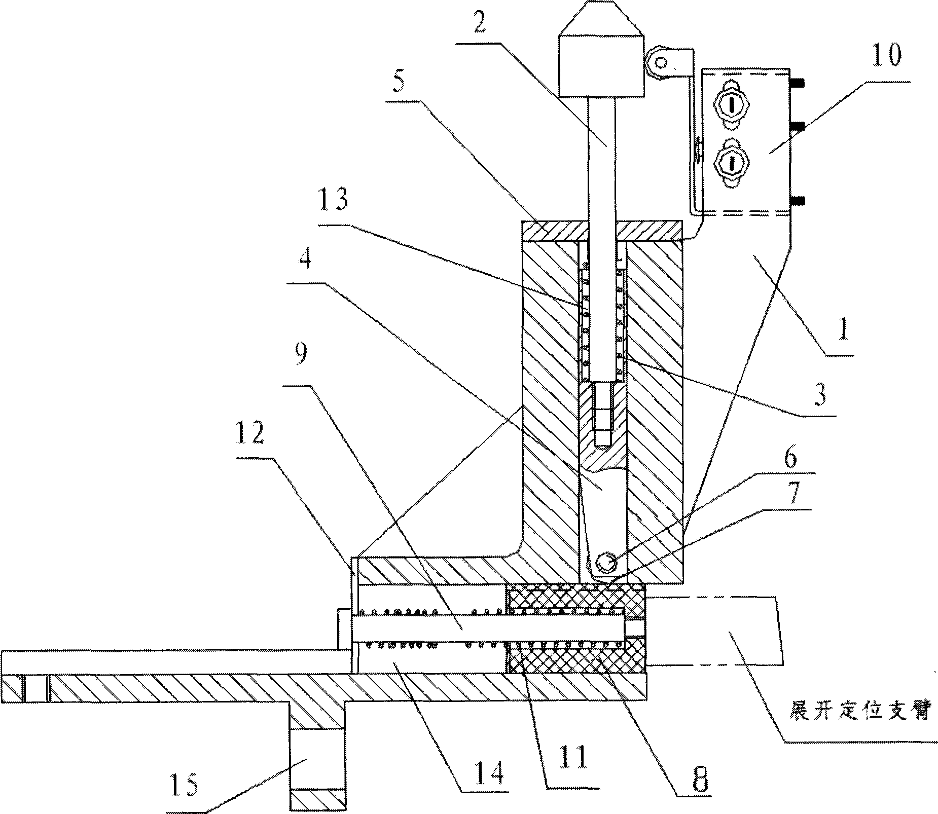
[0025] The present invention as figure 1 As shown, it includes the deployment positioning mechanism frame 1, the positioning stop pin guide rod 2, the stop pin thrust spring 3, the positioning stop pin 4, the stop pin block cover plate 5, the stop pin shaft 6, the stop pin roller 7, and the sliding pallet 8. Sliding pallet guide rod 9, micro switch 10, sliding pallet thrust spring 11 and guide cover 12.

[0026] The frame 1 of the deployment positioning mechanism is the main part of the deployment positioning mechanism, which provides support for other components. Through the installation hole 15 on it, the entire deployment positioning mechanism is installed on the satellite-borne antenna. The installation hole 15 adopts an oblong hole to facilitate the initial position adjustment.

[0027] Expanding positioning mechanism frame 1 has expanding positioning mechanism frame slot a13 and expanding positioning mechanism frame groove b14, positioning stop pin guide rod 2, stop pin...


PUM


Abstract

A satellite antenna expansion location mechanism comprises an expansion location mechanism frame, a location stop pin guide bar, a stop pin thrust spring, a location stop pin, a stop pin block cover board, a stop pin shaft, a stop pin roller, a sliding support plate, a guide bard, a sensitive switch, a sliding support plate thrust spring and a guide cover plate. The invention employs the sliding support plate instead of original sliding guide arc plate mounted inside the antenna support structure, and avoids external collisions in the antenna expansion process, and improves the safety. The invention can reduce a friction resistance during the antenna expansion process to make the antenna expansion more smoothly without contact friction force at the beginning of the antenna expansion. The antenna expansion location mechanism can be used for various satellite expansion antenna, specific and widely application fields.

Description

technical field [0001] The invention relates to a positioning and locking device for deploying an antenna reflector in place when a spaceborne large-scale deployable antenna is deployed on orbit, and belongs to the field of mechanical technology. Background technique [0002] Generally, large-scale space-borne antennas are expandable. They are in a folded and locked state before ground transportation and satellite launch into orbit. After entering orbit, the antenna reflector is unfolded under the drive of the unfolding mechanism. After unfolding in place, the antenna reflector is realized by unfolding the positioning mechanism. Positioning and locking on track. With the continuous development of satellite payloads, the caliber of space-borne antennas continues to increase. Due to the limitation of the carrying fairing, the large-aperture antennas are in a retracted state during launch. After entering orbit, the antenna reflectors are deployed. The deployment angle and prec...

Claims


Application Information

Patent Timeline
Patent Type & Authority Applications(China)
IPC IPC(8): H01Q1/08H01Q1/22H01Q1/28
Inventor 牛宝华宋剑鸣梁云郑士昆
Owner 中国航天科技集团公司第五研究院第五〇四研究所
Why Eureka
Try Eureka