
Survivable service flow conducting method based on interlayer message routing

A technology with survivability and traffic volume, applied in the field of communication network, it can solve the problems of large resource consumption, increased physical resources, long running time, etc.

Inactive Publication Date: 2009-07-08
UNIV OF ELECTRONICS SCI & TECH OF CHINA
View PDF0 Cites 16 Cited by
  • Summary
  • Abstract
  • Description
  • Claims
  • Application Information

AI Technical Summary

Problems solved by technology

[0013] 2) The inter-layer link mapping information H is used twice for calculation, and the resource increase on the physical link is superimposed as the weight of the virtual link. This weight setting method causes the weights on almost every virtual link to be relatively close to each other. , so that when routing services on the virtual topology, it is easy to add optical paths, resulting in an increase in physical resources
[0014] 3) It takes a long time to iterate for each business to find a route until the number of cycles ends or the spare capacity no longer decreases, which takes a long time to run
[0015] Existing survivability traffic grooming technology regards virtual topology design and service routing as two completely unrelated issues, and the weight setting method of service routing can easily lead to a large total resource consumption of the entire network resources, such a large resource consumption is usually unacceptable for most users

Method used


Image

  • Survivable service flow conducting method based on interlayer message routing
  • Survivable service flow conducting method based on interlayer message routing
  • Survivable service flow conducting method based on interlayer message routing

Examples


Embodiment Construction

[0079] A simple example is used below to illustrate the technical process of the present invention, mainly describing the link weight setting and resource allocation process when a service searches for a route in the upper layer virtual topology. In the present invention, we assume that the capacity of one wavelength is W=OC-48, and the normalized bandwidth is 48. Assume that there are three types of low-granularity services, OC-1, OC-3, and OC-12, and the normalized bandwidths are 1, 3, and 12 respectively.

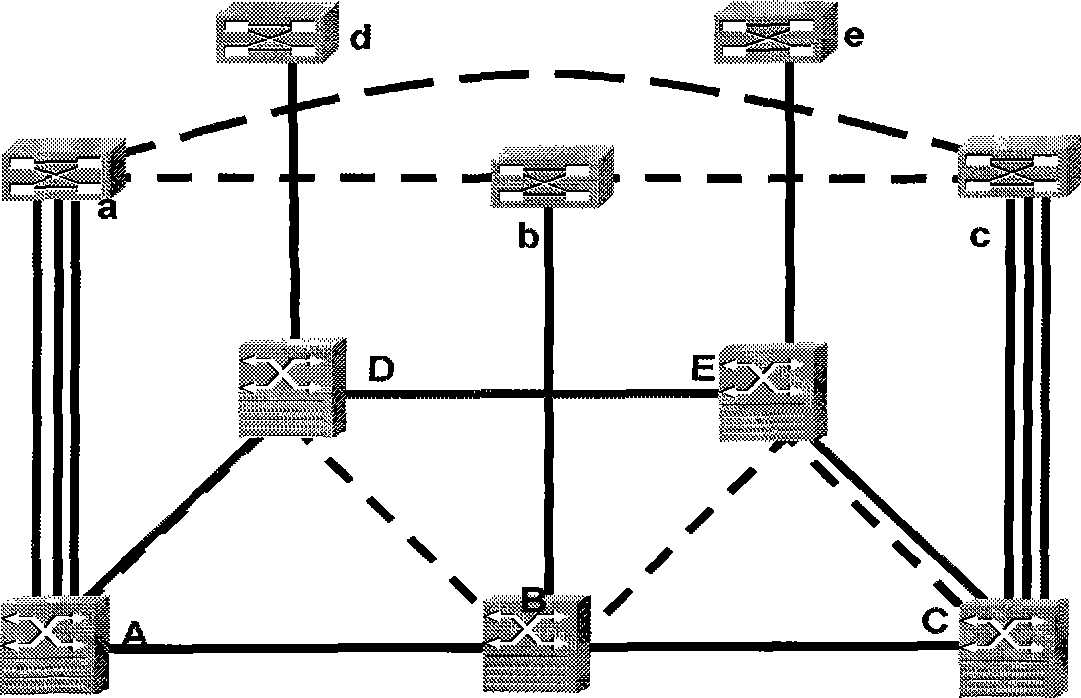
[0080] Physical topological network such as Image 6 As shown, it consists of 4 nodes and 5 links.

[0081] The existing 2 services as shown in Table 1 need to be in Image 6 The configuration in the network shown in the figure is aimed at minimizing the finally used physical network resources, that is, minimizing the number of occupied wavelengths on the physical topology network.

[0082] Business Number source node number destination node number bus...


PUM


Abstract

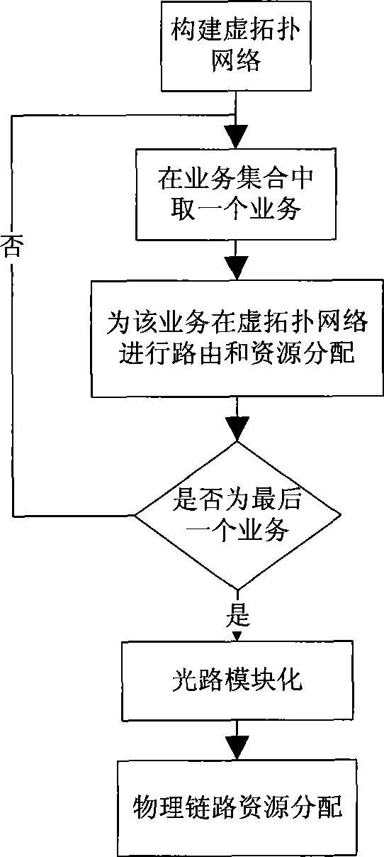
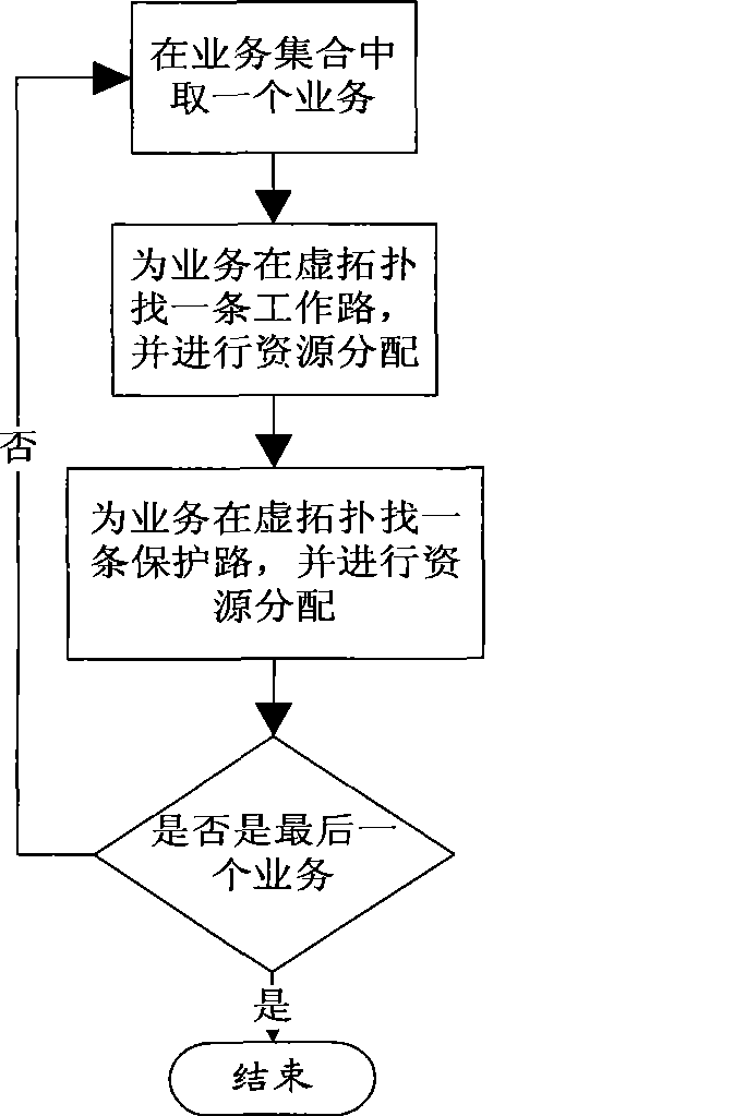
A survivability business dredging method based on interlayer message routing belongs to the technical field of communication network, and relates to an optical network business dredging technique and resource allocation method. The survivability business dredging method comprises the following steps: step1: constructing a virtual topological network according to a physical topological network structure; step 2: executing routing and resource allocation to each service in service aggregate in the virtual topological network; step 3: modularizing optical path; and step 4: allocating resource for physical chain in the physical topological network according to the optical path modularization result obtained in the step 3. According to the invention, at the state the connection state and service aggregate between the network node and the node is known, the routing is searched for service and resource is collocated based on the interlayer information. The usage of total resource in the physical network is reduced as possible. Furthermore the resource collocation speed is greatly increased. The invention is suitable for WDM optical network and is also suitable for two-layer and multi-layer network with different service granularities of the upper layer and the lower layer, for example: IP / MPLS over WDM network, two-layer SDH network, etc.

Description

technical field [0001] The invention belongs to the technical field of communication networks, and relates to an optical network service volume grooming technology and a resource allocation method. Background technique [0002] With the development of multi-layer network and optical network technology, the two-layer WDM optical transport network has become the core technology of the next-generation backbone network due to its huge transmission bandwidth. Since the bandwidth of many service requests in a WDM network is much smaller than the granularity of a wavelength, allocating an independent wavelength channel for each service request will seriously reduce network utilization. Therefore, it is necessary to aggregate multiple low-speed service requests in one Transmission on the wavelength channel, which is the so-called traffic grooming technology; at the same time, the huge transmission bandwidth is also facing challenges. Once the network components fail, a large amount ...

Claims


Application Information

Patent Timeline
IPC IPC(8): H04Q11/00H04J14/02H04J3/08
Inventor 虞红芳廖丹王丽陈士伟吴健
Owner UNIV OF ELECTRONICS SCI & TECH OF CHINA
Learn More