Multiple explosion prevention construction for electric capacitor
A technology of power capacitor and explosion-proof structure, which is applied in the field of power switchgear and can solve problems such as product failure
- Summary
- Abstract
- Description
- Claims
- Application Information
AI Technical Summary
Problems solved by technology
Method used
Image

Examples
Embodiment 1
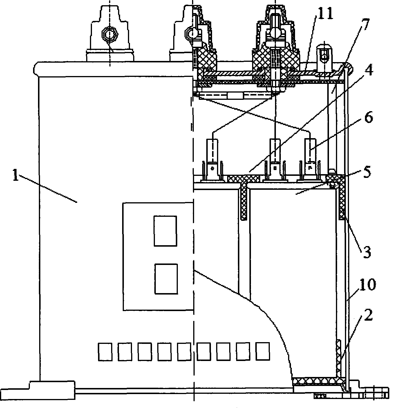
[0034] Such as figure 2 As shown, in the housing 10 of the power capacitor 1, a lower positioning sleeve 2 and an upper positioning sleeve 3 are set, and the two ends of the core group 4 are respectively covered by the lower positioning sleeve 2 and the upper positioning sleeve 3. fixed.
[0035] The core group 4 is fixed by a special upper and lower positioning sleeve technology. First, put each independent unit 5 that has been produced into the lower positioning sleeve 2 according to the requirements of the design documents and process documents, and then assemble the positioning sleeve 3, so that each independent unit 5 is firmly fixed in the horizontal direction Living.
[0036] The adoption of the above technical solution ensures the stability of the core group 4 in the vertical direction, and the core group 4 is firmly fixed in the horizontal and vertical directions. During production and processing, the installation is convenient, the positioning is accurate, the co...
Embodiment 2
[0038] Such as Figure 2 to Figure 6 As shown, the core group 4 of the present invention is respectively fixed by the lower positioning sleeve 2 and the upper positioning sleeve 3: the lower positioning sleeve 2 and the upper positioning sleeve 3 are all provided with the independent The shape of the end of the unit 5 is a corresponding concave cavity, the independent unit 5 is inserted into the concave cavity, and the side of the independent unit 5 forms an elastic tight fit with the concave cavity.
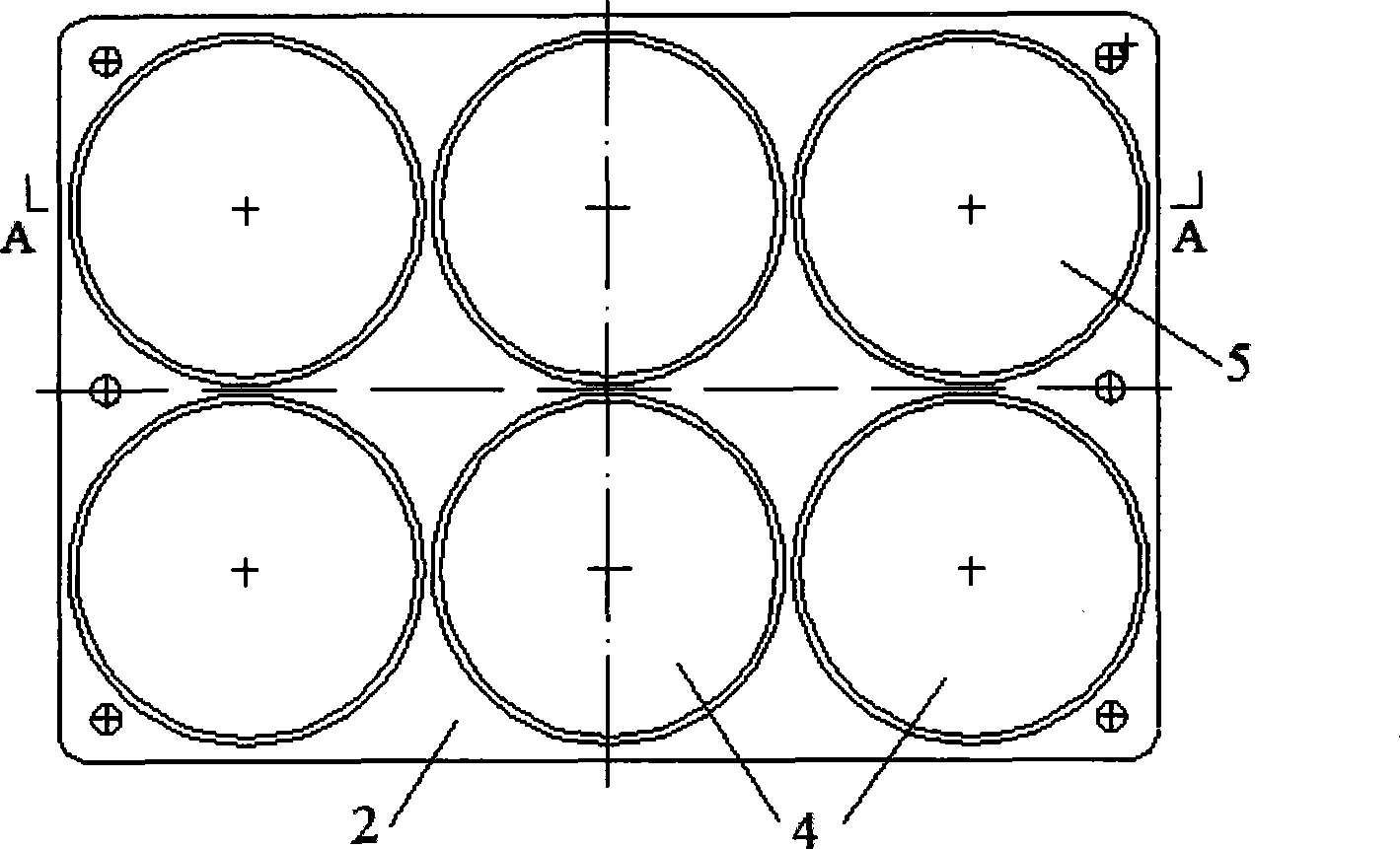
[0039] The lower positioning sleeve 2 and the upper positioning sleeve 3 are located on the same plane, and are provided with a plurality of concave cavities for installation. The plug-in structure is adopted to insert the independent unit 5, and each independent unit 5 is inserted through a tight fit with certain elasticity. The unit 5 is fixed, the position is accurate, it is not easy to loosen, and the installation is also very convenient.
Embodiment 3
[0041] The number of independent units 5 in the power capacitor 1 according to the present invention is equal to or more than three.
[0042] Each independent unit 5 of the present invention has anti-explosion mechanism, and the products of different specifications adopt the independent unit 5 that quantity is not equal, but have 3 independent units 5 at least.
PUM
 Abstract
Description
Claims
Application Information
 - R&D
- Intellectual Property
- Life Sciences
- Materials
- Tech Scout
- Unparalleled Data Quality
- Higher Quality Content
- 60% Fewer Hallucinations
Browse by: Latest US Patents, China's latest patents, Technical Efficacy Thesaurus, Application Domain, Technology Topic, Popular Technical Reports.
© 2025 PatSnap. All rights reserved.Legal|Privacy policy|Modern Slavery Act Transparency Statement|Sitemap|About US| Contact US: help@patsnap.com