A method and device for generating a driving current of a solenoid valve

A technique for driving and generating a solenoid valve, applied in the direction of valve operation/release devices, valve devices, electromagnets, etc., can solve the problems of weak control reliability, inability to effectively suppress interference, and low reliability, etc., and achieve circuit production Effect of low cost, shortened opening and closing time, and reduced fluctuation range

Inactive Publication Date: 2012-02-15
BEIJING INSTITUTE OF TECHNOLOGYGY
View PDF4 Cites 0 Cited by
  • Summary
  • Abstract
  • Description
  • Claims
  • Application Information

AI Technical Summary

Problems solved by technology

[0008] Furthermore, the reliability is not strong
In the traditional solenoid valve drive circuit, the sampling resistor is often located between the emitter of the low-end power triode and the power ground. This connection method cannot effectively suppress the interference on the power ground line, and the sampling voltage is generally less than 1V, so the sampling voltage is affected by interference. More obvious, weaker control reliability

Method used


Image

  • A method and device for generating a driving current of a solenoid valve
  • A method and device for generating a driving current of a solenoid valve
  • A method and device for generating a driving current of a solenoid valve

Examples


Embodiment Construction

[0045] The technical solutions of the present invention will be further described below in conjunction with the accompanying drawings and through specific implementation methods.
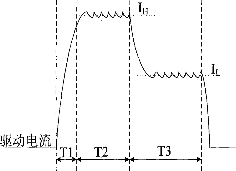
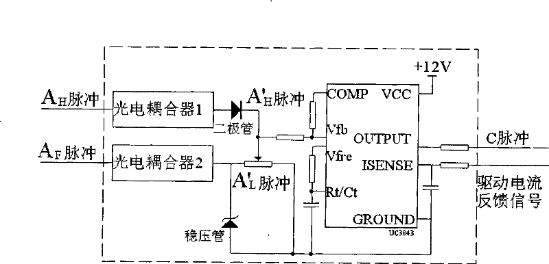
[0046] The main idea of ​​the technical solution of the present invention is to be applicable to the generating device of the solenoid valve drive current of the engine fuel injection system, including the electronic control unit, the signal processing circuit, the high-end drive circuit, the low-end drive circuit and the sampling resistor, and the high-end drive circuit passes the sampling resistor It is connected to one end of the solenoid valve, and the low-end drive circuit is connected to the other end of the solenoid valve. The electronic control unit sends a peak current holding control pulse signal A to the signal processing circuit. H and current feedback control pulse signal A F , and send the low-end drive circuit control pulse signal B to the low-end drive circuit. When the drive current...


PUM


Abstract

The invention discloses a method and device for generating driving current of a solenoid valve, which are suitable for an engine fuel injection system. A high-end drive circuit is connected to one end of the solenoid valve through a sampling resistor, and a low-end drive circuit is connected to the other end of the solenoid valve. An electronic control unit Send the peak current holding control pulse signal A11 and the current feedback control pulse signal AF to the signal processing circuit, and send the low-end drive circuit control pulse signal B to the low-end drive circuit, and the signal processing circuit compares the solenoid valve drive current fed back by the sampling resistor with the reference The current corresponding to the voltage is compared, and a control signal C is sent to the high-end drive circuit. Adopting the technical scheme of the present invention can shorten the opening time of the electromagnetic valve, the hardware current feedback control circuit is simple and reliable, the adjustment frequency is high, the anti-interference effect is good during use, and the price is low, and the overall production cost is low.

Description

technical field [0001] The invention relates to the technical field of electronically controlled engine fuel injection, in particular to a method and device for generating a driving current of an electromagnetic valve. Background technique [0002] In the electronically controlled engine fuel injection system, there are very strict requirements on the opening and closing of the solenoid valve. Since the opening and closing of the solenoid valve are closely related to the driving current, it is necessary to precisely control the driving current to realize the solenoid valve action. . [0003] figure 1 Is the schematic diagram of the solenoid valve drive current waveform. like figure 1 As shown, in the engine electromagnetic bypass valve control technology, the driving current is generally required to be in the form of figure 1 The two-stage drive current shown, T1 refers to the current boost stage, T2 current peak hold stage, T3 low current hold stage, the solenoid valve ...

Claims


Application Information

Patent Timeline
Patent Type & Authority Patents(China)
IPC IPC(8): H01F7/18F16K31/06
Inventor 刘波澜崔涛黄英张付军
Owner BEIJING INSTITUTE OF TECHNOLOGYGY
Why Eureka
Try Eureka