
Improved inner expansion type tube extension device

An internal expansion type and pipe technology, applied in the direction of workpiece clamping device, manufacturing tools, etc., can solve the problems of increased pipe consumption, high manufacturing cost, and increased processing procedures, so as to improve work efficiency, reduce subsequent processing procedures, and reliable processing Effect

Inactive Publication Date: 2009-07-08
WUXI HUAGUANG BOILER
View PDF0 Cites 6 Cited by
  • Summary
  • Abstract
  • Description
  • Claims
  • Application Information

AI Technical Summary

Problems solved by technology

Although this process can meet the needs of production conditions and ensure the processing quality of spiral finned tubes, but the processing steps increase, the amount of pipe materials increases, and the manufacturing cost is high.

Method used


Image

  • Improved inner expansion type tube extension device
  • Improved inner expansion type tube extension device
  • Improved inner expansion type tube extension device

Examples


Embodiment Construction

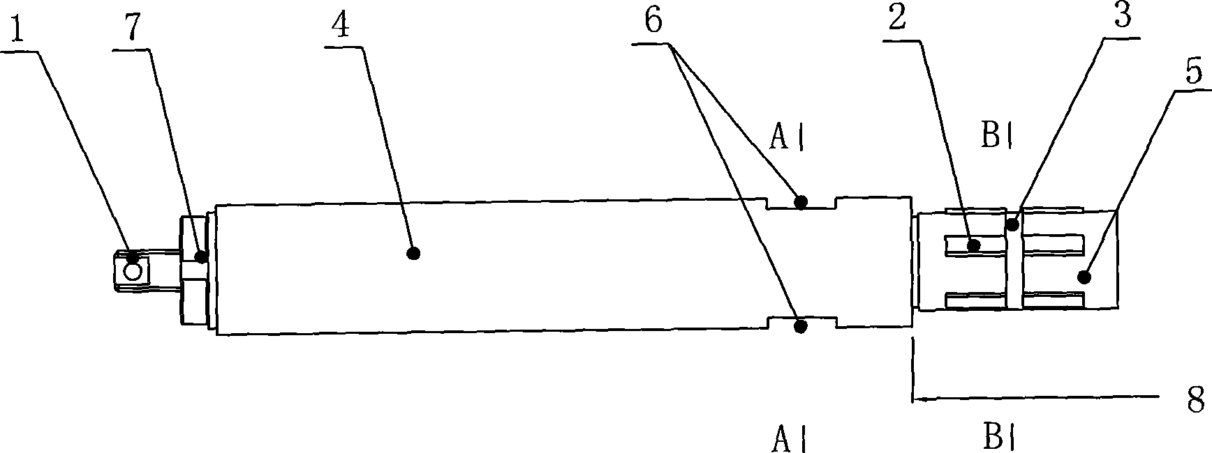
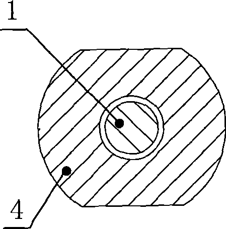
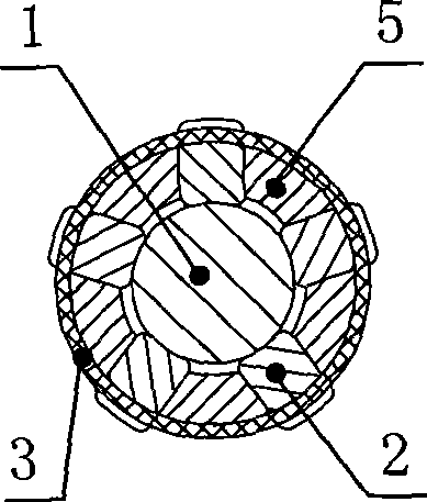
[0011] See figure 1 , figure 2 , image 3 and Figure 4 , the present invention includes a sleeve, an inner tie rod 1, an expansion block 2 and an elastic ferrule 3, the sleeve includes a connection part 4 and an expansion joint part 5, the inner tie rod 1 is set inside the sleeve, and the sleeve expansion joint part 5 A sliding groove is formed along the circumference, the expansion block 2 is embedded in the sliding groove, and the elastic ferrule 3 is sleeved on the periphery of the expansion joint part 5 of the sleeve. The inner tie rod 1 has an oblique cone structure at the expansion joint part 5 of the sleeve; the inner tie rod 1 and the sleeve are connected and fixed by the lock nut 7; there are five sliding grooves; five expansion blocks 2 are arranged; The outer diameter of the connecting part 4 of the sleeve is the same as that of the finned tube to be processed; the connection between the connecting part 4 of the sleeve and the joint part 5 is a step surface, an...


PUM


Abstract

The invention provides an improved internal expanded tube extender. The tube extender can greatly reduce tube process margin length in machining spiral finned tubes, reduce subsequent finned tube machining procedures, improve the work efficiency and lower the manufacturing cost. The tube extender comprises a sleeve, an internal draw bar, an expansion block and an elastic ferrule, the sleeve comprises a tube connecting part and an expansion joint part, the internal draw bar is sheathed inside the sleeve, the expansion joint part of the sleeve is provided with a sliding groove along a circumferential direction, the expansion block is embedded in the sliding groove, and the elastic ferrule is sheathed on the periphery of the expansion joint part of the sleeve.

Description

(1) Technical field [0001] The invention relates to the field of pipe lengthening tooling, in particular to an improved internal expansion type pipe lengthening device. (2) Background technology [0002] During the processing of spiral finned tubes, due to the equipment structure of the production line and the welding conditions, a space distance of more than 200mm should be left between the fin winding welding part and the tube clamping rotating walking power head, and the required length of the tube clamping is 100mm. , for each spiral finned tube, the distance between the winding end of the tube and the welding point of the spiral fin should not be less than 350mm during processing. The distance between fin winding and welding is mostly 110mm. For this reason, the conventional production method is to add more than 250mm process length to the product structure length of each spiral finned tube, and remove the process margin after winding and welding. Although this process...

Claims


Application Information

Patent Timeline
Patent Type & Authority Applications(China)
IPC IPC(8): B21C37/26B25B11/00
Inventor 范凯
Owner WUXI HUAGUANG BOILER
Learn More