
Method, device and system for measuring SDH network element transmission time delay and clock synchronization

A technology of transmission delay and network element, which is applied in the field of communication and can solve problems such as inability to accurately measure

Active Publication Date: 2009-07-01
DATANG MOBILE COMM EQUIP CO LTD
View PDF0 Cites 7 Cited by
  • Summary
  • Abstract
  • Description
  • Claims
  • Application Information

AI Technical Summary

Problems solved by technology

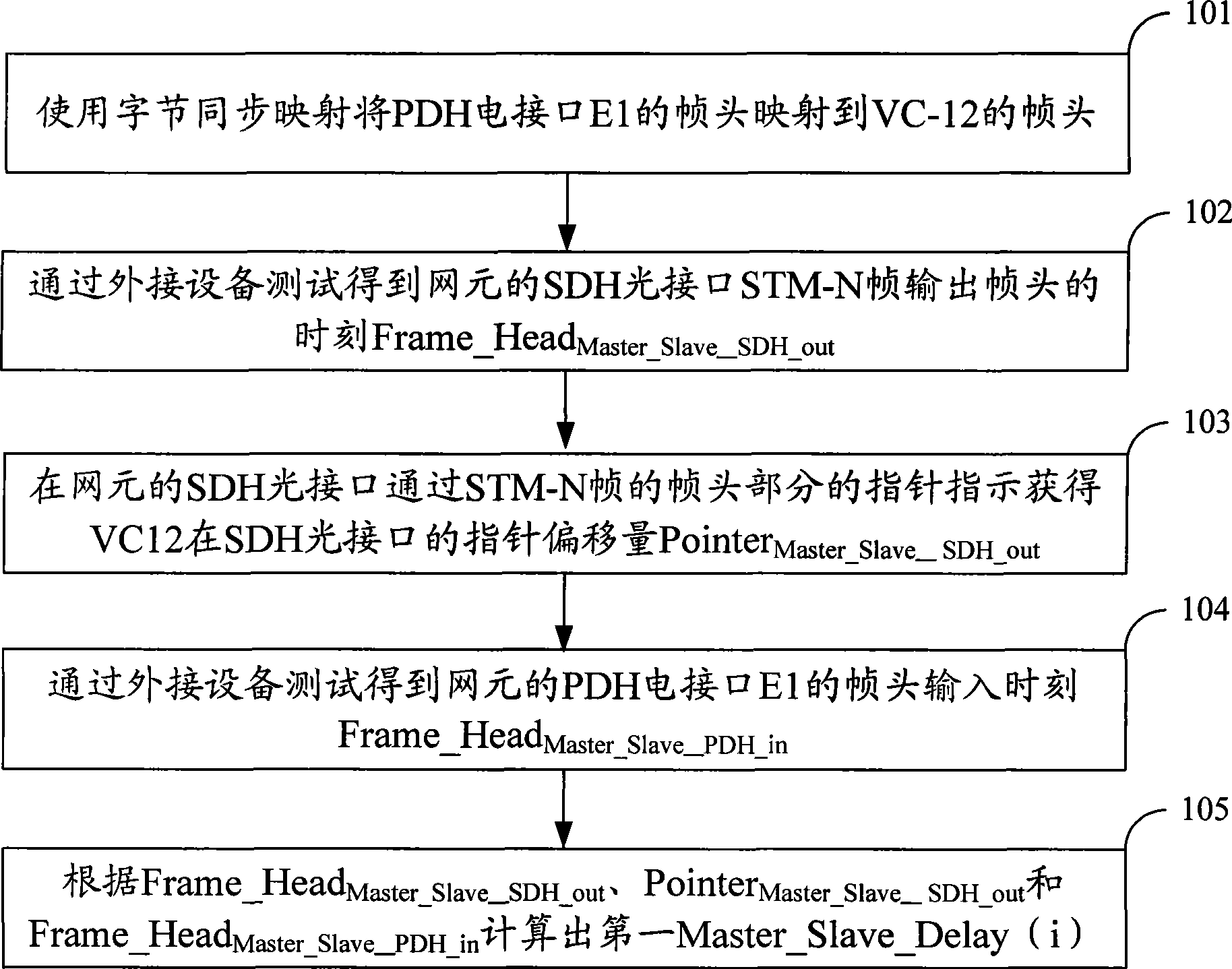
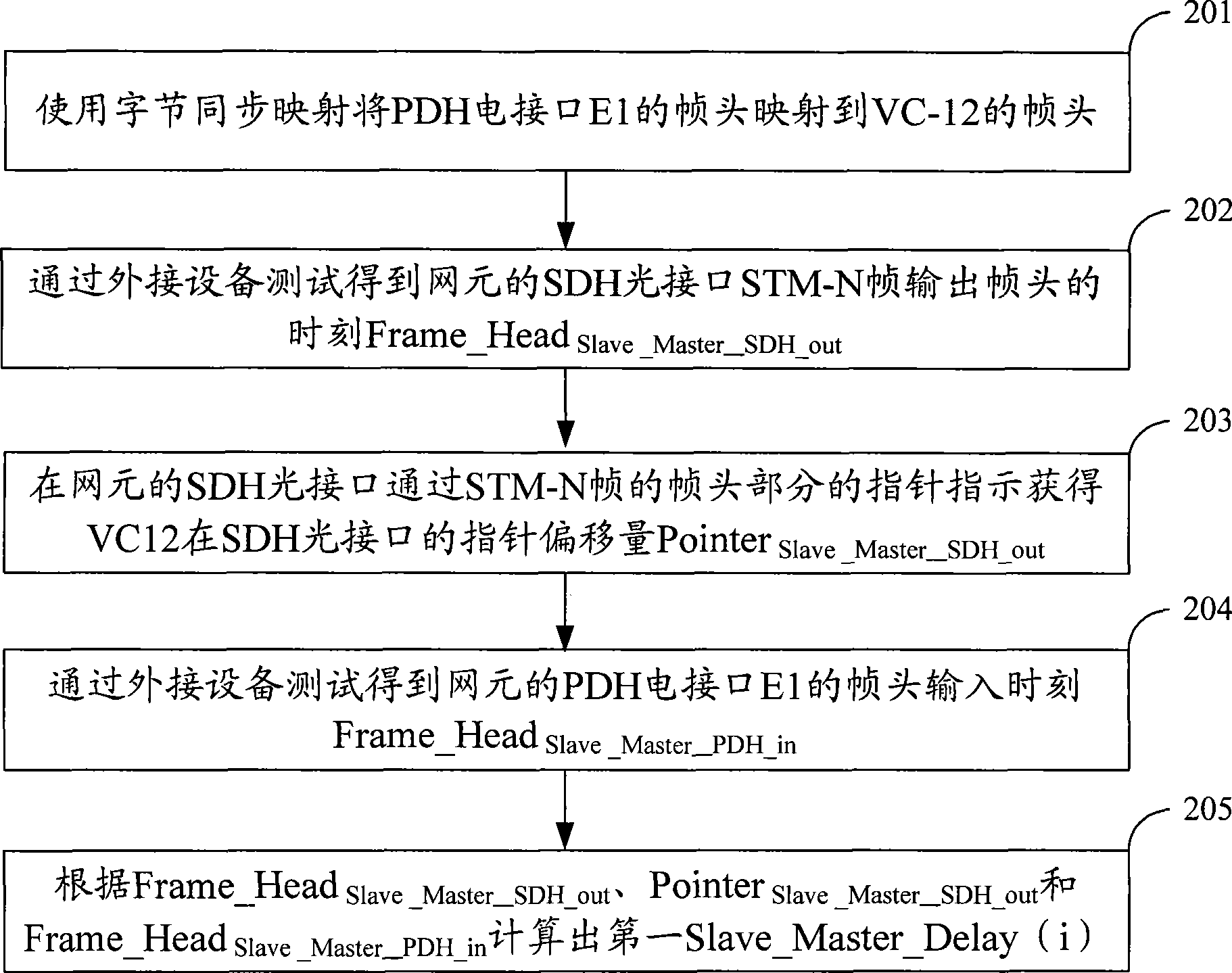
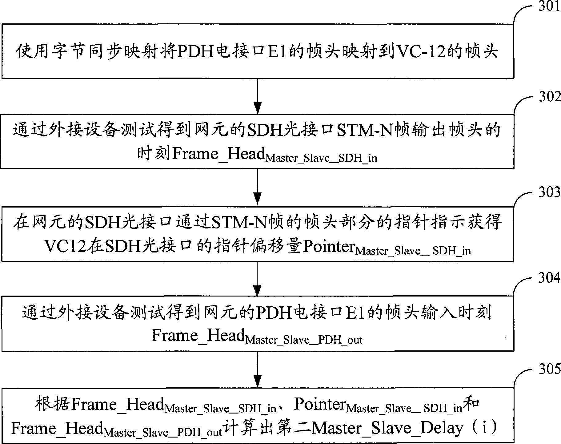
[0003] In order to solve the problem in the prior art that it is impossible to accurately measure the message interaction by using E1, the interactive message is the optical interface of SDH on one side, and the transmission delay of the network element of the electrical interface of PDH on the other side, the present invention implements The example provides a method for measuring the transmission delay of SDH network elements, which is suitable for SDH network elements with SDH optical interfaces on one side and PDH electrical interfaces on the other side, including:

Method used


Image

  • Method, device and system for measuring SDH network element transmission time delay and clock synchronization
  • Method, device and system for measuring SDH network element transmission time delay and clock synchronization
  • Method, device and system for measuring SDH network element transmission time delay and clock synchronization

Examples


Embodiment Construction

[0031] In order to enable those skilled in the art to better understand the solution of the present invention, the present invention will be further described in detail below in conjunction with the accompanying drawings and embodiments. In the following, during the clock signal transmission process, the message carrying the clock signal is described in the direction from the master clock source to the slave clock source, and from the slave clock source to the master clock source as an example. The process is similar when using E1 to realize other message exchanges, and the transmission delay of SDH network elements is also measured from two directions of message exchange.

[0032] The first embodiment provided by the present invention is a method for measuring the transmission delay of an SDH network element. In this embodiment, the measurement is an SDH network element with an SDH optical interface on one side and a PDH electrical interface on the other side. The interface i...


PUM


Abstract

The invention discloses a method for detecting the transmission delay and the clock synchronization of a synchronous digital hierarchy (SDH) network element, and a device and a system thereof, which solve the problem that the prior art fails to accurately detect the transmission delay of a network element when utilizing the E1 to implement the message interaction, wherein an SDH optical interface is arranged at one side of the network element and a plesiochronous digital hierarchy (PDH) electrical interface is arranged at the other side of the network element. The method comprises the following steps: mapping the frame header of the PDH signal of the PDH electrical interface to the frame header of a virtual container by means of byte synchronization mapping; measuring the first moment of transmitting the frame header of the PDH signal of the PDH electrical interface through the PDH electrical interface; measuring the second moment of transmitting the frame header of the virtual container corresponding to the SDH optical interface in a synchronous transmission module level N (STM-N) frame relative to the frame header of the STM-N; and calculating the transmission delay of the SDH network element according to the first moment, the second moment and the time offset. By adopting the byte synchronization mapping mode, the method can determine the shared test point of the input and the output and can calculate the transmission delay of the SDH network element.

Description

technical field [0001] The invention belongs to the technical field of communication, in particular to a method, device and system for measuring SDH network element transmission delay and clock synchronization. Background technique [0002] Existing communication systems, such as 3G, telephone switches, routers, etc., are mostly carried on a time division multiplexing (Time Division Multiplexing, TDM) transmission network. The TDM transmission network includes a synchronous digital hierarchy (Synchronous Digital Hierarchy, SDH) and / or a quasi-synchronous digital hierarchy (Plesiochronous Digital Hierarchy, PDH) network. Among them, E1 is the frame structure of the digital transmission link stipulated by the International Telecommunications Union, which is widely used in Europe, and this standard is also adopted in my country. An N-level synchronous transmission module level N (Synchronous Transmission Module level N, STM-N) frame may be used to carry the E1, specifically, t...

Claims


Application Information

Patent Timeline
IPC IPC(8): H04J3/06
Inventor 谢子阳
Owner DATANG MOBILE COMM EQUIP CO LTD
Learn More