
Automatic control type traffic light control system

A traffic light control and traffic light technology, applied in traffic control systems, traffic control systems for road vehicles, and traffic signal control, etc., can solve the problem of inability to actively adapt to traffic conditions, inability to adjust control parameters, and inability to constantly optimize intersection traffic control state and other issues, to achieve the effect of being conducive to smooth flow, improving traffic capacity, and being beneficial to roads

Inactive Publication Date: 2009-07-01
AOCHENGTONGLI S&T DEV BEIJING
View PDF0 Cites 40 Cited by
  • Summary
  • Abstract
  • Description
  • Claims
  • Application Information

AI Technical Summary

Problems solved by technology

[0002] The existing traffic light control system is set in the cabinet located on the side of the traffic light road, and the action of the traffic light switch is controlled by the central control unit to realize the sequential conversion of the traffic lights. The control system is equipped with a parameter setting input device and a forced switch device. Input and control the control parameters such as traffic light switching sequence and switching time, and realize the direct control of traffic lights by people through the forced switch device. The defect of this technology is that the control parameters cannot be automatically adjusted according to the traffic flow in each direction. Finally, no matter how the traffic situation changes in each time period, it cannot actively adapt to the traffic situation, so that the traffic control at the intersection cannot always be in the best state.

Method used


Image

  • Automatic control type traffic light control system

Examples


Embodiment Construction

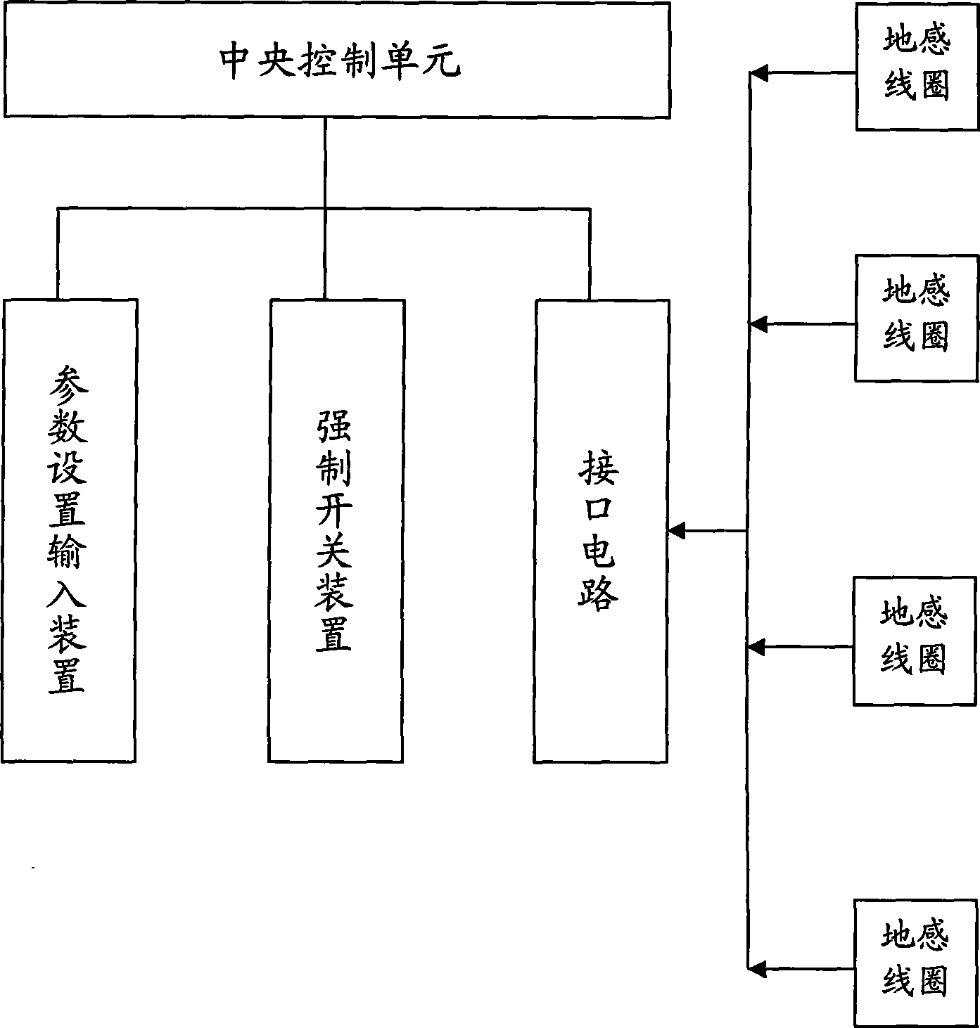
[0007] see figure 1 , the present invention provides a self-controlled traffic light control system, including a central control unit for controlling the traffic light switch action, the central control unit is provided with a parameter setting input device, a forced switch device and a multi-stage ground induction coil detection device, the The multi-level coil detection device is mainly composed of a plurality of ground induction coils distributed under the ground along the road extension direction. There is a certain distance between the local induction coils, and the signal output lines of the local induction coils are connected to the corresponding interface circuit. The central control unit sends a vehicle detection signal to the central processing unit, and the central processing unit analyzes and calculates the vehicle detection signal, judges whether there is a vehicle on the road and the driving state of the vehicle, and calculates the number of stationary vehicles on...


PUM


Abstract

The invention relates to a self-controlled type traffic light control system, which comprises a central control unit which is used to control switching actions of traffic lights, wherein the central control unit is provided with a parameter setting and inputting device, a forced switch device and a multistage induction coil detecting device, wherein the multistage induction coil detecting device is mainly composed of a plurality of induction coils which are distributed underground along the extending direction of a road, wherein certain distance is left between the induction coils, a signal output line of each induction coil is switched into the central control unit through a corresponding interface circuit, a vehicle detecting signal is sent to a central processing unit, the central processing unit is used to analyze and operate the vehicle detecting signal, and the vehicle releasing time on different directions and the releasing order on each direction can be automatically adjusted according to the difference of the static vehicle queuing length of each road. The control system can automatically adjust a traffic light control parameter according to traffic flow changes on different directions to improve the traffic efficiency of intersections and to realize the optimum control to the intersection traffic.

Description

technical field [0001] The invention relates to a self-controlled traffic light control system, which is mainly used for controlling traffic signal lights. technical background [0002] The existing traffic light control system is set in the cabinet located on the side of the traffic light road, and the action of the traffic light switch is controlled by the central control unit to realize the sequential conversion of the traffic lights. The control system is equipped with a parameter setting input device and a forced switch device. Input and control the control parameters such as traffic light switching sequence and switching time, and realize the direct control of traffic lights by people through the forced switch device. The defect of this technology is that the control parameters cannot be automatically adjusted according to the traffic flow in each direction. Finally, no matter how the traffic conditions change in each time period, they cannot actively adapt to the traf...

Claims


Application Information

Patent Timeline
IPC IPC(8): G08G1/08G08G1/042G08B13/08H05K7/20
Inventor 梁治龙
Owner AOCHENGTONGLI S&T DEV BEIJING
Learn More