
Laser cutting control method

A control method, laser cutting technology, applied in the direction of digital control, laser welding equipment, electrical program control, etc., can solve the problem that the machine tool cannot run continuously, achieve the effect of improving cutting efficiency, reducing alarm frequency, and avoiding alarm

Inactive Publication Date: 2009-07-01
HANS LASER TECH IND GRP CO LTD
View PDF0 Cites 8 Cited by
  • Summary
  • Abstract
  • Description
  • Claims
  • Application Information

AI Technical Summary

Problems solved by technology

[0002] Existing laser cutting machine tools will produce some pore slag and whiskers of pore slag after perforating thick plates (above 3MM) stainless steel plates, and these pore slag and pore slag whiskers are easy to contact under the action of protective gas To the height sensor of the laser cutting head, the sensor collision protection triggers an alarm and interrupts the cutting process, making the machine tool unable to run continuously

Method used


Image

  • Laser cutting control method
  • Laser cutting control method

Examples


Embodiment Construction

[0012] The following content is a further detailed description of the present invention in conjunction with specific preferred embodiments, and it cannot be assumed that the specific implementation of the present invention is limited to these descriptions. For those of ordinary skill in the technical field of the present invention, without departing from the concept of the present invention, some simple deduction or replacement can be made, which should be regarded as belonging to the protection scope of the present invention.

[0013] The laser cutting control method of the present invention is aimed at laser cutting machine tools, which will produce hole slag and whiskers of hole slag after the thick plate (above 3MM) stainless steel plate is perforated, which is easy to touch the laser cutting head height sensor, causing the sensor to collide and protect the alarm. Interrupt the cutting process. In order to make the cutting go on normally, it is necessary to eliminate some ...


PUM


Abstract

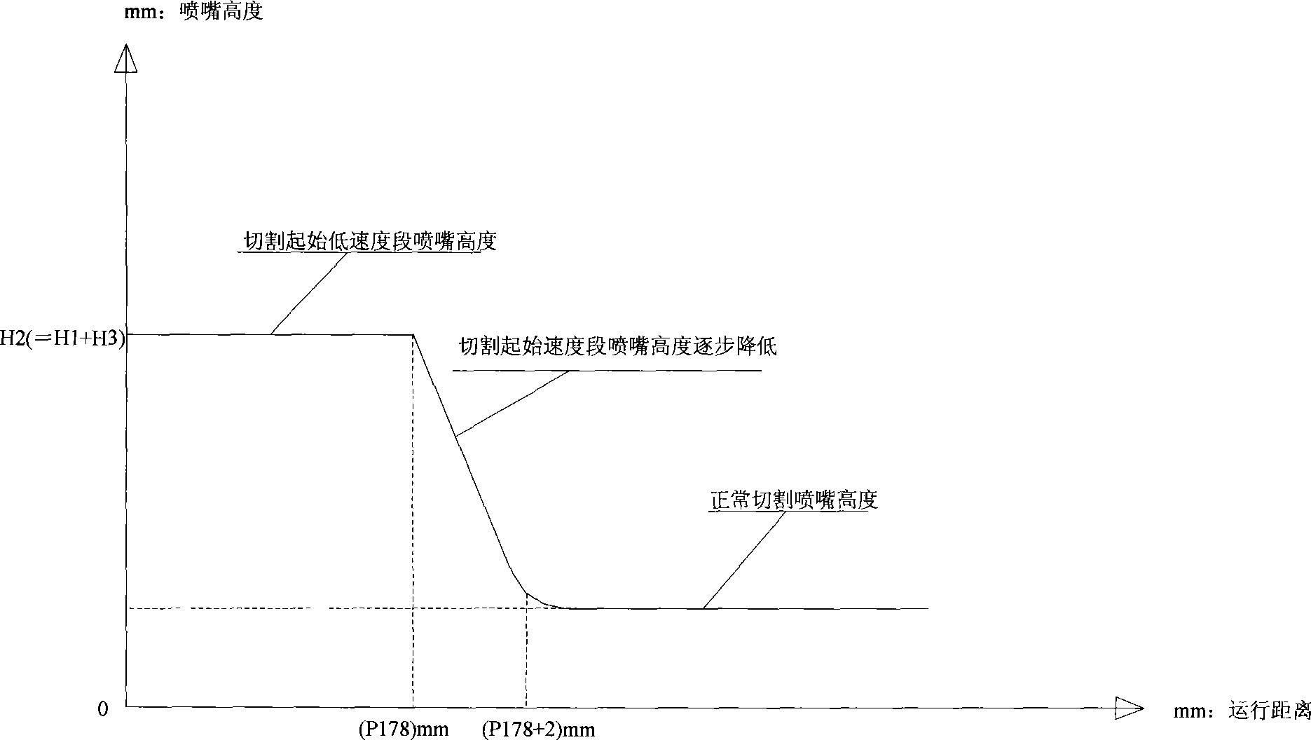
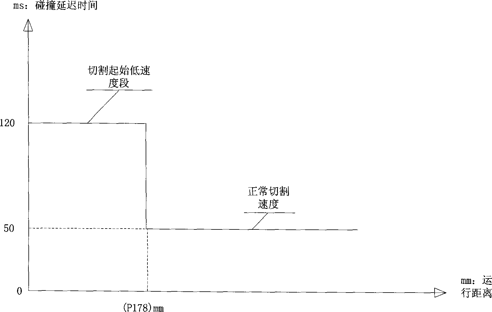
The invention provides a method for controlling laser cutting, which comprises the following steps: presetting the height of a cutting nozzle deviating from board to be higher one offset height than the height of a normal cutting nozzle in the initial stage; and recovering a laser cutting head nozzle to the height of the normal cutting nozzle after a laser cutting head sensor deviates from the hole slag range distance according to a path movement track. The method for controlling laser cutting can make a laser cutting machine adopt the height of the cutting nozzle deviating from the board in the initial cutting stage and increase the delay time of an alarming sensor, so as to reduce the alarming frequency of collision protection of the cutting track in the initial stage, avoid unnecessary alarm and improve the whole cutting efficiency. A laser cutting machine tool can be favorably guided into the normal cutting state.

Description

technical field [0001] The invention relates to a laser work control method, in particular to a laser cutting control method. Background technique [0002] Existing laser cutting machine tools will produce some pore slag and whiskers of pore slag after perforating thick plates (above 3MM) stainless steel plates, and these pore slag and pore slag whiskers are easy to contact under the action of protective gas To the height sensor of the laser cutting head, the sensor collision protection triggers an alarm and interrupts the cutting process, making the machine tool unable to run continuously. Contents of the invention [0003] In order to overcome the shortcomings of the above-mentioned prior art, the present invention provides a laser cutting control method that can make the laser cutting machine tool transition smoothly to the normal cutting state at the initial stage of cutting. [0004] The technical solution adopted by the present invention to solve the technical probl...

Claims


Application Information

Patent Timeline
Patent Type & Authority Applications(China)
IPC IPC(8): B23K26/00G05B19/18B23K26/042
Inventor 高云峰向水平
Owner HANS LASER TECH IND GRP CO LTD
Learn More