Radiating device

A heat dissipation device and heat dissipation fin technology, which is applied in cooling/ventilation/heating transformation, instruments, electrical digital data processing, etc., and can solve the problems of reduced heat dissipation efficiency of heat dissipation devices, low heat dissipation efficiency, and low utilization rate of cold air

Inactive Publication Date: 2011-11-09
HONG FU JIN PRECISION IND (SHENZHEN) CO LTD +1
View PDF0 Cites 0 Cited by
  • Summary
  • Abstract
  • Description
  • Claims
  • Application Information

AI Technical Summary

Problems solved by technology

[0004] In the above heat dissipation device, the airflow blown by the fan flows along the intervals between the heat sinks, and leaves the heat sink group in a very short time, the utilization rate of cold air is low, so that the heat dissipation efficiency is low; and the above heat dissipation device Since the fixing of the fan requires complex structure erection, the fan can only be installed on one side of the heat sink, resulting in weaker air flow on the other side of the heat sink group, resulting in reduced heat dissipation efficiency of the entire heat sink

Method used


Image

  • Radiating device
  • Radiating device
  • Radiating device

Examples


Embodiment Construction

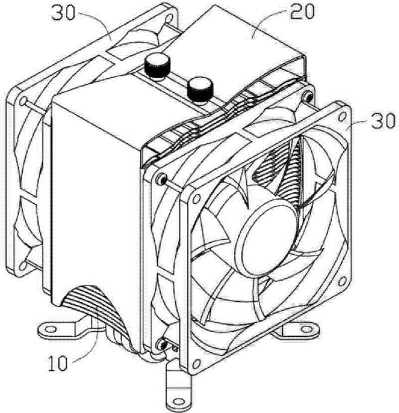
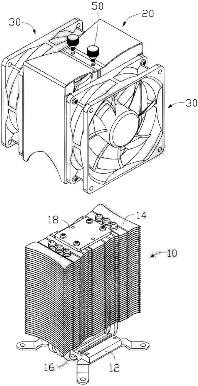
[0013] Please also refer to figure 1 and figure 2 , is the heat dissipation device of the first embodiment of the present invention, the heat dissipation device is installed on a circuit board (not shown in the figure) to dissipate the heat generated by the electronic components (not shown in the figure) on the circuit board. The heat dissipation device includes a radiator assembly 10 , an air guide cover 20 assembled on the radiator assembly 10 , and two fans 30 installed on opposite sides of the air guide cover 20 .

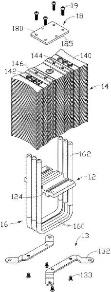
[0014] Please also refer to image 3 , the heat sink assembly 10 includes a heat conduction plate 12, a heat dissipation fin group 14, three heat pipes 16 arranged in parallel for connecting the heat conduction plate 12 and the heat dissipation fin group 14, and a fixing member fixed on the top of the heat dissipation fin group 14 plate 18, wherein:

[0015] The heat conduction plate 12 is roughly in the shape of a rectangular plate, and three parallel groo...


PUM


Abstract

The present invention relates to a heat radiator used for heat dissipation of electronic components, comprising a heat-conducting plate which is adhibited with the electronic components, a plurality of radiating fins, and a heat pipe used for connecting the heat-conducting plate and the radiating fins, wherein, a plurality of air channels are formed among the radiating fins. The heat radiator further comprises a wind scooper. The wind scooper comprises a top plate and two baffles, wherein, the two baffles are connected with the top plate; the top plate is fixed at the top part of the radiating fins; the baffles surround the two ends of the radiating fins; two fans are fixed on the wind scooper and arranged at the two sides of the radiating fins and at the inlet and the outlet of the air channels. A mounting part is extended out from on both sides of each baffle of the wind scooper. And the fans are fixed on the mounting parts. By adopting the structure that the wind scooper surrounds the radiating fins and the two fans, the convection intensity of the air in the gas channel of the radiating fins is enhanced and the heat dissipation efficiency of the heat radiator is improved.

Description

technical field [0001] The invention relates to a cooling device, in particular to a cooling device for cooling electronic components. Background technique [0002] High-power electronic components such as computer central processing unit, north bridge chip, and graphics card will generate a lot of heat during operation. If the heat cannot be effectively dissipated, the temperature will directly rise sharply, which will seriously affect the normal operation of electronic components. . For this reason, a heat sink is needed to dissipate heat from these electronic components. [0003] A traditional cooling device usually includes a base, a heat sink set, a heat pipe connecting the base and the heat sink set, and a fan fixed on one side of the heat sink set. The heat generated by the electronic components is first transferred to the base, and then absorbed by the bottom of the heat pipe; the heat pipe transfers the heat to its end through the phase change of the working fluid...

Claims


Application Information

Patent Timeline
Patent Type & Authority Patents(China)
IPC IPC(8): H05K7/20H01L23/34H01L23/467G06F1/20
Inventor 徐宏博
Owner HONG FU JIN PRECISION IND (SHENZHEN) CO LTD
Why Eureka
Try Eureka