Integrated cooling and power generation device driven by thermal energy
What is Al technical title?
Al technical title is built by PatSnap Al team. It summarizes the technical point description of the patent document.
A technology of thermal energy and refrigerators, which is applied in the field of new refrigerator generators, can solve the problems of low refrigeration efficiency, immature technology, and large investment, and achieve the effects of improving refrigeration efficiency, output efficiency, and reliability
Inactive Publication Date: 2012-02-22
SOUTHEAST UNIV
View PDF0 Cites 0 Cited by
Summary
Abstract
Description
Claims
Application Information
AI Technical Summary
This helps you quickly interpret patents by identifying the three key elements:
Problems solved by technology
Method used
Benefits of technology
Problems solved by technology
Absorption refrigeration requires a heat source temperature above 120°C, which is only suitable for large projects, with large investment and low efficiency
Adsorption and thermoacoustic refrigeration have low efficiency and immature technology
[0004] Data query found a patent (CA101187509A) on the direct use of thermal energy to realize cogeneration of power generation and refrigeration. This patent uses steam injection to compress the circulating working medium of the refrigerator. In addition to the disadvantage of low efficiency, the heat engine and refrigerant can only use the same A variety of working fluids, which cannot meet the needs of different heat source temperatures and different refrigeration temperatures
Method used
Image
Click on the blue label to locate the original text in one second.
Reading with bidirectional positioning of images and text.
Examples
Embodiment Construction
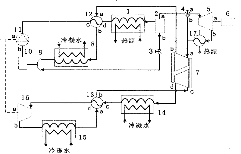
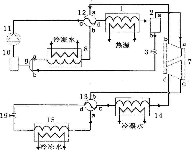
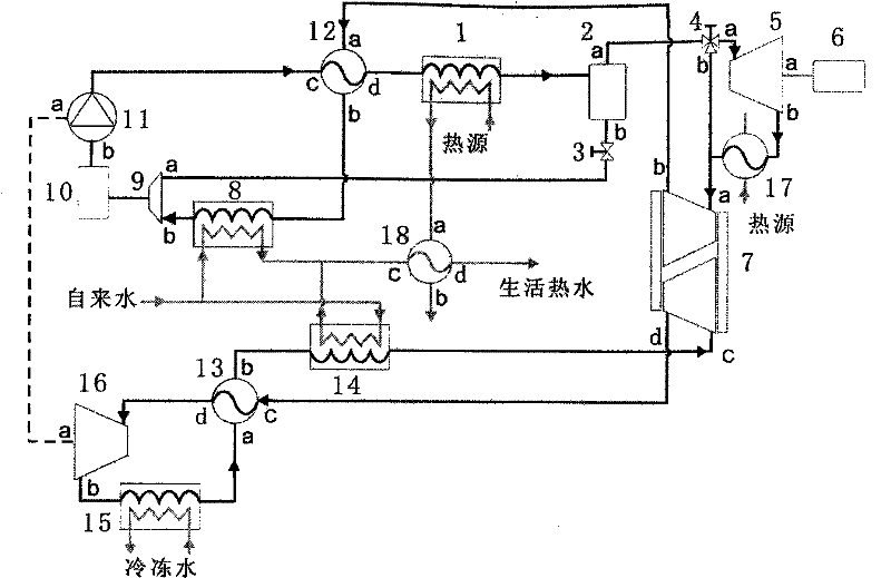
[0032] figure 1 Among them, the device consists of two parts: a heat engine driven by heat energy and a refrigerator. The thermal engine consists of a steam generator 1, a vapor-liquid separator 2, a two-way valve 3, a three-way valve 4, a turbine 5, a generator 6, a pressure exchanger 7, a first condenser 8, a confluence 9, and a liquid reservoir 10. The circulating pump 11, the first vapor-liquid heat exchanger 12, and the reheater 17 are connected as follows: the outlet of the gaseous working medium of the steam generator 1 is connected to the inlet of the vapor-liquid separator 2, and the outlet of the liquid working medium of the vapor-liquid separator is connected to 2b The inlet of the two-way valve 3, the outlet 2a of the gaseous working medium of the gas-liquid separator is connected to the inlet of the three-way valve 4, the first outlet 4a of the three-way valve is connected to the inlet of the turbine 5, the output shaft of the turbine 5a is coaxially connected wit...
PUM
Abstract
The heat-driven refrigeration and power generation integrated device is composed of a heat engine and a refrigerator. The heat engine includes a circulating pump, a steam generator, a vapor-liquid separator, a two-way valve, a three-way valve, a turbine, a generator, a pressure exchanger, a first vapor-liquid heat exchanger, a first condenser, a confluence device, a storage Liquid tank, reheater. The heat engine uses heat energy to generate high-pressure steam, which drives compression refrigeration and drives turbines and generators to generate electricity. The refrigerator includes an evaporator, a second vapor-liquid heat exchanger, a pressure exchanger, a second condenser, and an expander. The shaft work output of the refrigerator expander is used to drive the circulation pump. The working fluids of the heat engine and the refrigerator can be the same or different, and non-azeotropic working fluids can be used to improve efficiency. The invention can use low-grade heat sources, and can be adjusted to separate cooling, combined cooling and power supply, or combined cooling, heating and power supply according to the temperature of the heat source. It has the advantages of high efficiency, less investment, short installation period, and low maintenance costs.
Description
technical field [0001] The invention relates to a new type of refrigerator generator device, in particular to a device that utilizes thermal energy to directly drive vapor compression refrigeration and can simultaneously generate electricity and heat. Background technique [0002] The energy consumption of refrigeration and HVAC has already accounted for more than a quarter of the electricity in the whole society. The development of alternative energy sources for refrigeration equipment and the improvement of the energy efficiency ratio of refrigeration equipment are related to the great cause of sustainable development. How to use renewable energy and industrial waste heat in refrigeration technology, directly drive refrigeration equipment with heat energy, and build a joint system of distributed refrigeration and power generation has always been an alternative energy solution that people expect. The emergence of this technology not only saves electricity and fossil fuels, ...
Claims
Application Information
Patent Timeline
Application Date:The date an application was filed.
Publication Date:The date a patent or application was officially published.
First Publication Date:The earliest publication date of a patent with the same application number.
Issue Date:Publication date of the patent grant document.
PCT Entry Date:The Entry date of PCT National Phase.
Estimated Expiry Date:The statutory expiry date of a patent right according to the Patent Law, and it is the longest term of protection that the patent right can achieve without the termination of the patent right due to other reasons(Term extension factor has been taken into account ).
Invalid Date:Actual expiry date is based on effective date or publication date of legal transaction data of invalid patent.