
Milling and drilling machine comprising a pallet exchanger

A pallet exchange, program-controlled technology, applied in the direction of manufacturing tools, metal processing machinery parts, other manufacturing equipment/tools, etc., can solve the problems of lifting mechanism pollution, failure, failure, etc., to prevent fluid pollution and reduce error quotas , the effect of preventing debris accumulation

Active Publication Date: 2009-06-17
普夫隆腾德克尔-马豪有限责任公司
View PDF0 Cites 14 Cited by
  • Summary
  • Abstract
  • Description
  • Claims
  • Application Information

AI Technical Summary

Problems solved by technology

In the pallet changers used hitherto, the lifting mechanism for raising and lowering the pallets is located in the protective cabin of the machine tool, which leads to the absence that individual parts of the lifting mechanism may be damaged due to work in the protective cabin. Contaminated by fluid and debris
Accumulation of debris on relatively moving parts of the lift and swivel mechanism can lead to failure and failure
In unmanned change operations, failure of the pallet changer inevitably leads to failure of the entire machine

Method used


Image

  • Milling and drilling machine comprising a pallet exchanger
  • Milling and drilling machine comprising a pallet exchanger
  • Milling and drilling machine comprising a pallet exchanger

Examples


Embodiment Construction

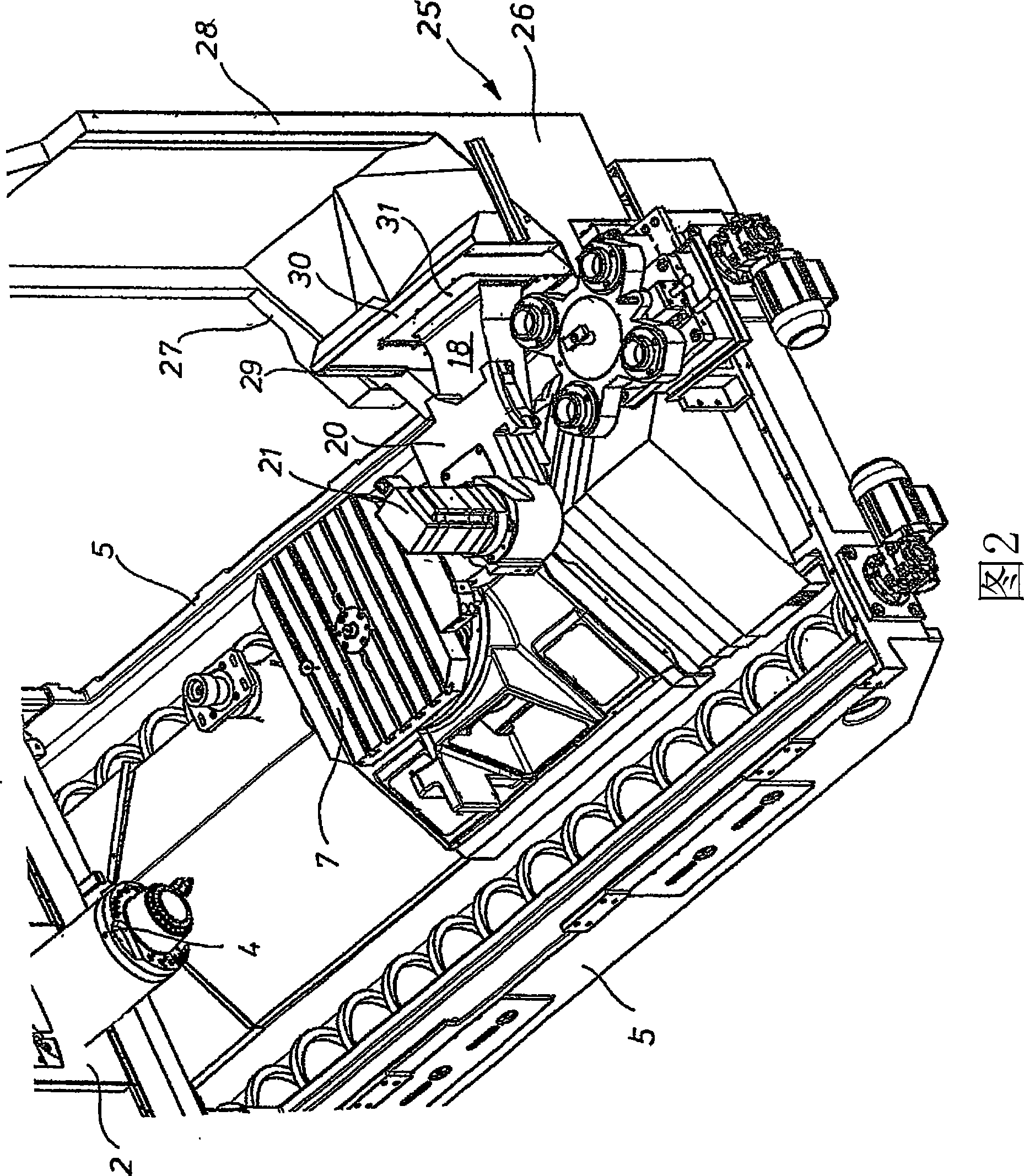
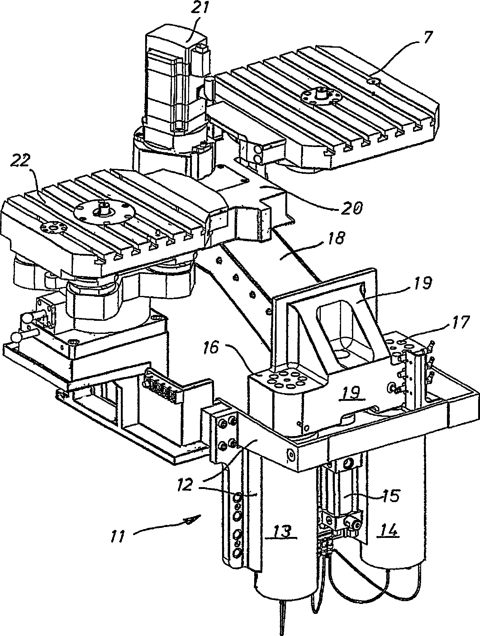
[0015] The front part of the milling-drilling machine shown in Figures 1 and 2 comprises a machining column 1 (not shown in detail in the present case) covered by a steel sheet frame 2 provided with a milling head comprising a horizontal milling head in the present case 4 work units 3. The working unit 3 can be moved along the coordinate axes X and Y by being driven by a motor. A bed 5 is installed in front of the processing column 1 , and a workpiece carrier 6 including a workpiece pallet 7 is arranged on the bed. The workpiece carrier 6 together with the pallet 7 can be moved by the motor in the longitudinal direction of the bed 5 , ie along the coordinate axis Y.

[0016] At the left end portion of the bed 5 in FIG. 1, a pallet exchange device 10 is provided, which will be described in more detail below. The pallet changer detailed in FIGS. 1 to 3 comprises a lifting mechanism 11 arranged at the side walls of the bed 5 and comprising a load carrying mechanism 12 . In thi...


PUM


Abstract

The invention relates to a program-controlled milling and drilling machine comprising a machine column, a machining unit comprising a milling head and being movable along at least one coordinate axis at the front of the machine column, a machine bed disposed in front of the machine column, a work carrier movable on the machine bed along another coordinate axis, and a pallet exchanger arranged at the free end portion of the machine bed, having two spaced apart pallet holders and a rotating and lifting mechanism on a joint load-bearing structure. According to the invention, the load-bearing structure of the pallet exchanger is laterally arranged next to the machine bed and has a dimensionally stable and sturdy transverse arm extending across the machine bed and supporting the rotating mechanism, the lifting mechanism in the load-bearing structure laterally arranged next to the machine bed being arranged in a manner so as to protect against dirt by a splashboard.

Description

technical field [0001] The invention relates to a program-controlled milling and drilling machine comprising a fixed machine column with a machining unit having: a milling head movable along at least one coordinate axis at the front of the machine column; A bed at the front of the machining column; a workpiece carrier traveling along the coordinate axis on the bed; and a pallet changer disposed at an end portion of the bed and having two pallet holders and a rotation and raising mechanism. Background technique [0002] For continuous machining of workpieces, milling and drilling machines are usually equipped with a pallet changer, which enables workpieces to be exchanged in a short time, increasing chip throughput while reducing non-cutting time. The pallet loads the workpieces outside the machine tool and is detachably attached to or at the pallet carrier of the pallet changer. In the pallet changer mentioned here, the pallets are attached by lowering and shifting, the mou...

Claims


Application Information

Patent Timeline
IPC IPC(8): B23Q7/02B23Q1/25B23P23/02
CPCB23Q1/4876Y10S29/056B23Q1/66Y10S29/094Y10T409/30868Y10T409/30392Y10T29/5196B23Q7/1431
Inventor 罗伯特·荣格
Owner 普夫隆腾德克尔-马豪有限责任公司
Learn More