
Protection device for laser welding head

A laser welding head and protection device technology, which is applied in laser welding equipment, welding equipment, metal processing equipment, etc., can solve the problems of focusing mirror pollution, achieve the effects of avoiding pollution, protecting weld seams, and prolonging life

Inactive Publication Date: 2012-01-25
INST OF MECHANICS - CHINESE ACAD OF SCI
View PDF4 Cites 2 Cited by
  • Summary
  • Abstract
  • Description
  • Claims
  • Application Information

AI Technical Summary

Problems solved by technology

[0009] The purpose of the present invention is to overcome the shortcomings of the above-mentioned prior art, thereby providing a method that can not only solve the pollution problem of the focusing mirror in the laser welding process, but also protect the welding seam on the basis of not affecting the beam transmission in the laser welding process. A protective device for the laser welding head of the integration of the area

Method used


Image

  • Protection device for laser welding head
  • Protection device for laser welding head
  • Protection device for laser welding head

Examples


Embodiment 1

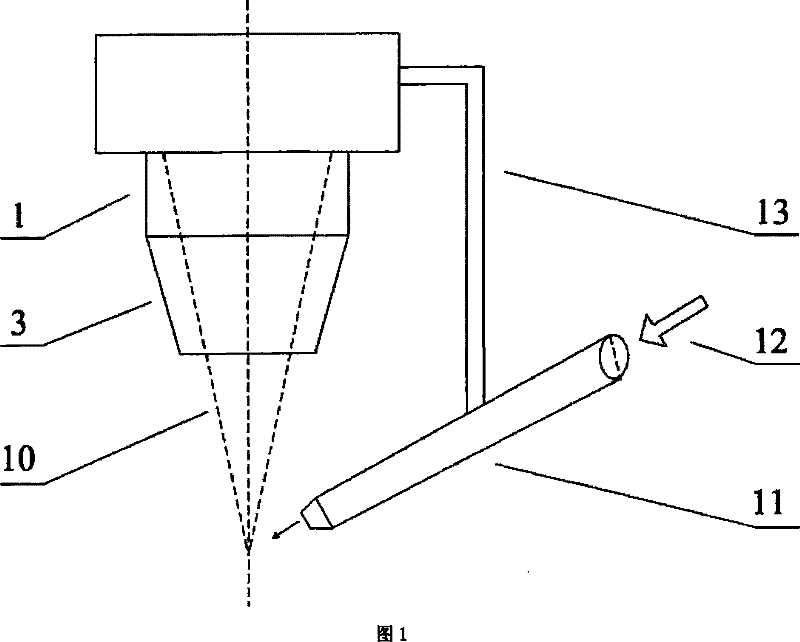
[0039] refer to figure 1 , make a protective device of the present invention, which is composed of a body 14 and a side-blowing protective gas nozzle; the side-blowing protector nozzle 11 is fixed on the protective device body 14 through a fixed bracket 13, such as a movable joint.

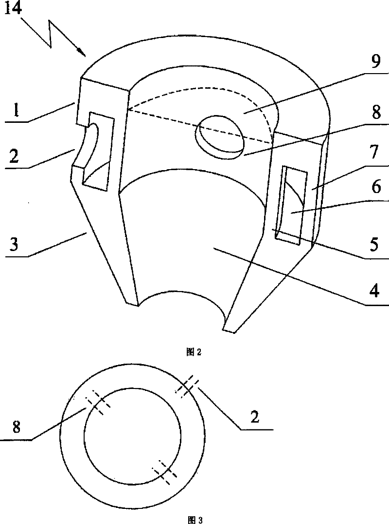
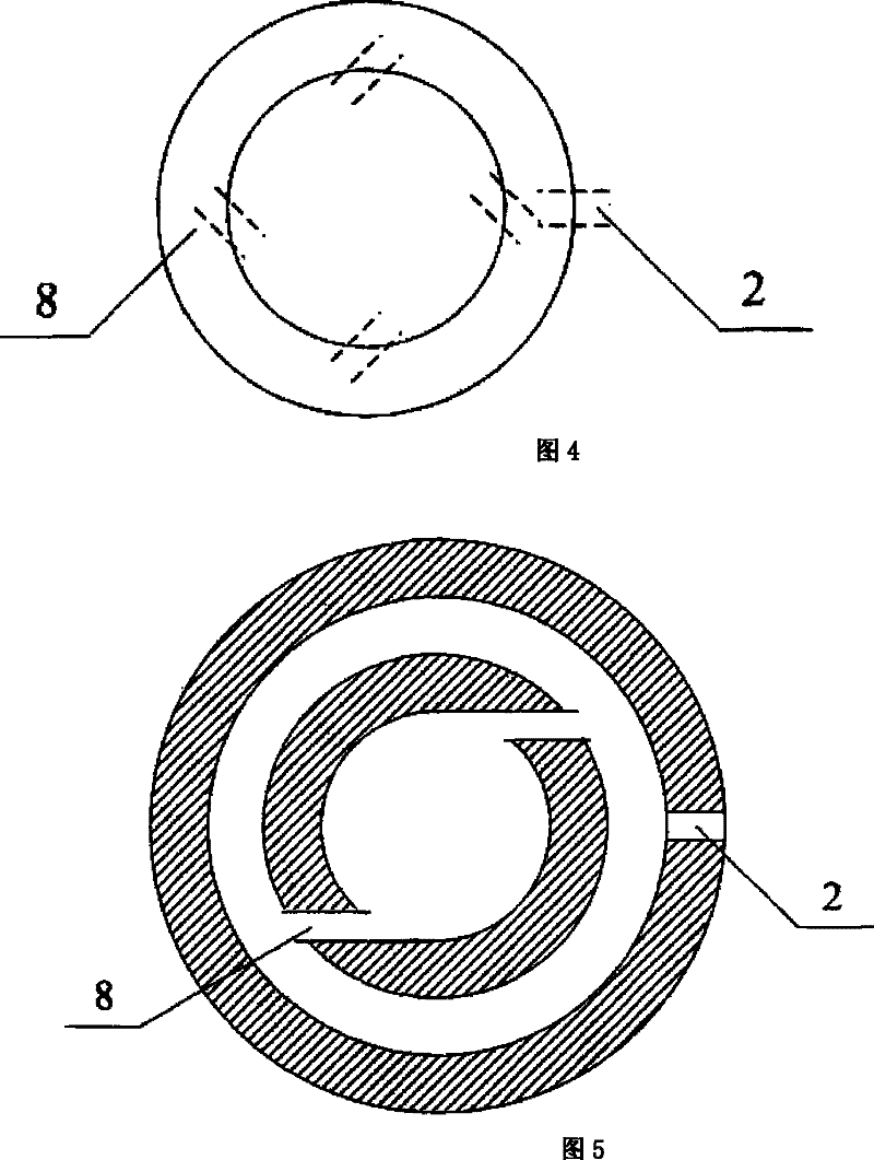
[0040] refer to figure 2 , 3 , the body of the protective device is made of aluminum cylindrical tube 1 and conical tube 3 are integrated into one. The external diameter that makes cylindrical tube 1 is for example 70, 90 or 100mm, and internal diameter is for example 50, 55 or 60mm; Wherein, cylindrical tube 1 top external diameter is 80mm, and internal diameter is 50mm; Cylindrical tube 1 bottom outer ring 7 The outer diameter of the cylinder is 80mm, and the inner diameter is 75mm; the outer diameter of the lower inner ring 5 of the cylindrical tube 1 is 55mm, and the inner diameter is 50mm. The inner diameter of the upper opening of the conical cylinder 3 is 50 mm, the inner diameter of th...

Embodiment 2

[0043] Add 4 air inlets 8 in the shielding gas on the device made by embodiment 1, as Figure 4 shown. Wherein the setting of shielding gas inlet 8 forms a certain angle according to the axis of the air inlet in the shielding gas and the tangent line of the wall surface of circular tube inner ring 5, the angle range is 0°-90° (parallel-vertical), the taper of conical tube 3 It is 1:6.

Embodiment 3

[0045] Open 2 air inlets 8 in the shielding gas on the device made by embodiment 1, as Figure 5 shown. Wherein the air inlet 8 in the shielding gas is set according to the parallel horizontal opening of the shielding gas along the tangent line to the outer surface of the cylinder inflatable, and the taper of the conical tube 3 is 1:4.


PUM


Abstract

The invention relates to a simple protection device for laser welding, which comprises a bracket. One end of the bracket is fixed on an upper port of the body, while the other end is connected with a protective gas nozzle by a freely movable joint. The body consists of a cavity, wherein the upper side of the cavity is a cylinder which extends to be a conical body. The central position of the inner wall of the cylinder is provided with a circular passage with the circular cross section as a circular plenum chamber, and the circular plenum chamber divides the cylinder into an outer ring of the cylinder and an inner ring of the cylinder, wherein the wall of the outer ring of the cylinder is provided with M protective gas inlets, and the wall of the inner ring of the cylinder is provided withN outer air inlets of protective gas, and protective lens for protecting laser focus lens are horizontally arranged on the inner wall of the upper part of the cylinder. On the basis of not influencing the beam transmission in the process of laser welding, the simple protection device solves the pollution problem of the focus lens in the process of laser welding with the function of protecting welding seams.

Description

technical field [0001] The invention relates to a component for laser welding, in particular to a protection device for a laser welding head. Background technique [0002] At present, in the process of laser welding, the dust, smoke and other sputters generated by welding are unavoidable. These dusts are easy to attach to the surface of the focusing lens, which reduces the transmittance of the focusing lens and contaminates the focusing lens. Reduce the service life of the focusing lens. During the welding process, the weld seam and its surrounding high-temperature areas are extremely susceptible to oxidation, and the use of inert gas to protect the molten pool during welding is a commonly used method at present. From the above situation, it can be seen that how to effectively protect the focusing lens without affecting or better protecting the weld pool is a problem that must be solved. [0003] The current laser welding head protection device mainly uses protective lense...

Claims


Application Information

Patent Timeline
Patent Type & Authority Patents(China)
IPC IPC(8): B23K26/14B23K26/20
Inventor 虞钢王恒海宁伟健王立新郑彩云宋宏伟
Owner INST OF MECHANICS - CHINESE ACAD OF SCI
Learn More