Power terminal having built-in power terminal
A technology for power terminals and power modules, which is applied to output power conversion devices, electrical components, electrical solid devices, etc., can solve problems such as increasing management and manufacturing costs, and achieve the effect of reducing costs and simplifying the bonding process.
- Summary
- Abstract
- Description
- Claims
- Application Information
AI Technical Summary
Problems solved by technology
Method used
Image
Examples
Embodiment 1
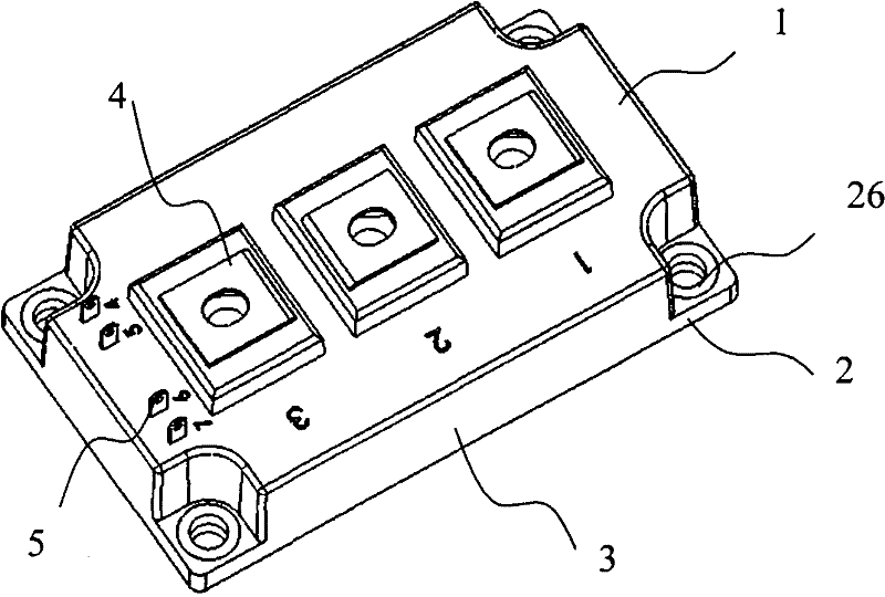
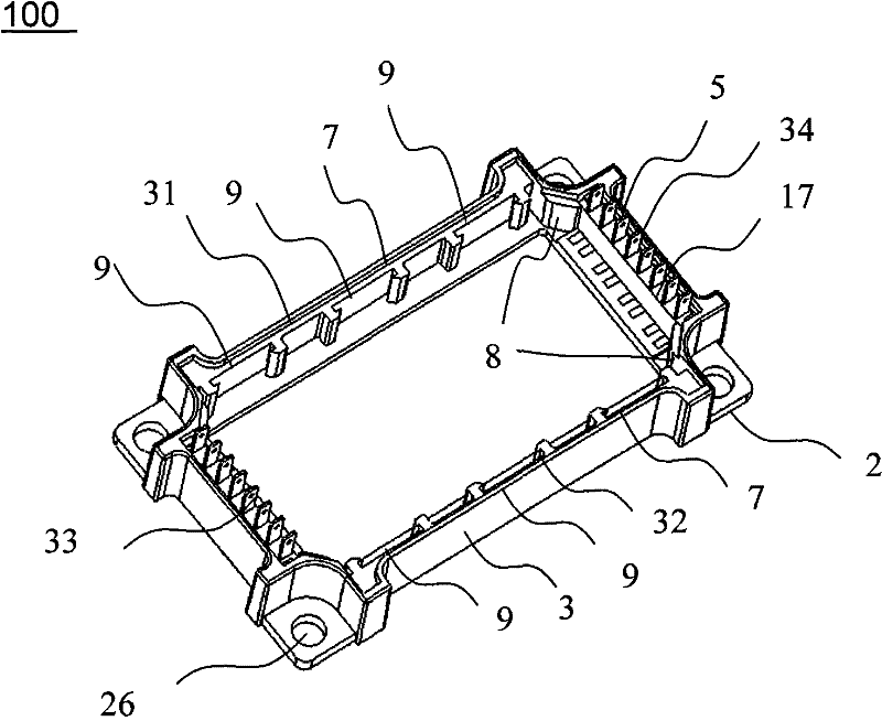
[0025] Such as figure 2 As shown, the power module 100 with embedded power terminals includes a top cover, a bottom plate 2 , a frame 3 , power terminals 4 and signal terminals 5 , and a power terminal bracket 7 and a signal terminal bracket 6 . The four corners of the bottom plate 2 are provided with mounting positioning holes 26, and the bottom plate is provided with a DBC substrate and a chip. The power terminal brackets 7 are arranged inside the front and rear sides 31, 32 of the frame 3, and molded together with the inside of the frame 3. Three slots 9 are respectively provided on the two power terminal brackets 7.
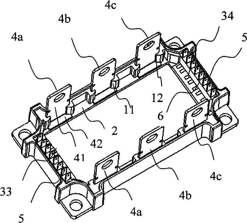
[0026] Such as image 3 As shown, the power terminals 4 are inserted into the three slots 9 at the front side 31 of the frame, the main body 41 of the power terminals is disposed in the slots 9 , and the bottom 42 of the power terminals is bonded to the bottom plate 2 . The notch 11 of the slot is provided with a bend 12, and the bend surface forms a 45° w...
Embodiment 2
[0031] The difference between this embodiment and the above example is that this embodiment is provided with three power terminals 4 .
[0032] Such as Figure 5 As shown, in this embodiment, a first power terminal 4a, a second power terminal 4b, and a third power terminal 4c are respectively provided in three slots 9 located inside the front edge 31 of the frame. The two signal terminal brackets 6 are respectively embedded in the inner side of the left side 33 and the right side 34 of the frame 3, and the two ends of the left side 33 and the right side 34 are provided with stoppers 8 for the positioning of the signal terminal bracket 6, and the two signal terminal brackets 6 are respectively Two signal terminals 5 are provided.
[0033] In this embodiment, the power module can directly replace the standard "34mm" power module under the condition that the installation positioning hole remains unchanged.
Embodiment 3
[0035] In this embodiment, the power module has a half-bridge structure.
[0036] Such as Image 6 As shown, there are three slots 9 located in the front side 31 of the frame 3, and are respectively provided with a first power terminal 4a, a second power terminal 4b, and a third power terminal 4c, which serve as U, V, and W output power terminals respectively. Leading out, two signal terminals 5 are respectively provided on the two signal terminal brackets in the left side 33 of the frame 3 .
PUM
 Abstract
Description
Claims
Application Information
 - R&D Engineer
- R&D Manager
- IP Professional
- Industry Leading Data Capabilities
- Powerful AI technology
- Patent DNA Extraction
Browse by: Latest US Patents, China's latest patents, Technical Efficacy Thesaurus, Application Domain, Technology Topic, Popular Technical Reports.
© 2024 PatSnap. All rights reserved.Legal|Privacy policy|Modern Slavery Act Transparency Statement|Sitemap|About US| Contact US: help@patsnap.com


