
A depolarised WDM source

一种波分复用、偏振复用的技术,应用在超长距离传输通信系统中的使用领域,达到高OSNR、减轻破坏性后果、准确波长和功率控制的效果

Inactive Publication Date: 2009-06-03
X TRILLION COMM CO LTD
View PDF1 Cites 2 Cited by
  • Summary
  • Abstract
  • Description
  • Claims
  • Application Information

AI Technical Summary

Problems solved by technology

To make matters worse, changes in channel power can affect the optical signal-to-noise ratio (OSNR) of the channel and the strength of nonlinear effects resulting in changes in the bit error rate (BER) performance of the channel

Method used


Image

  • A depolarised WDM source
  • A depolarised WDM source
  • A depolarised WDM source

Examples


Embodiment Construction

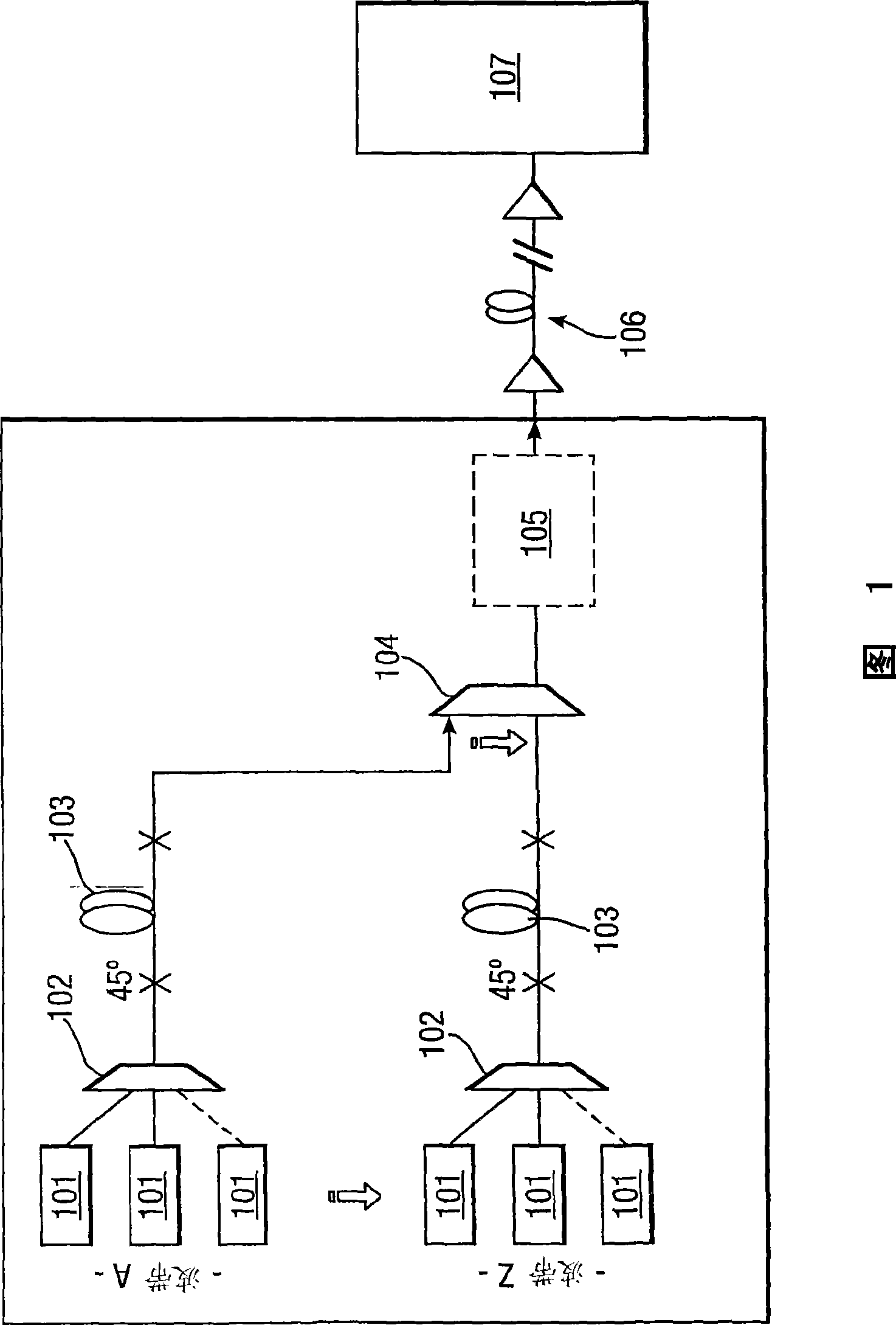
[0037] Figure 1 shows a typical example of a Submarine Line Terminal Equipment (SLTE) transmission system. These channels can be any combination of loading and data channels. In the example shown, there are separate "wave bands", each of which includes multiple channels. A WMD signal is formed from each band before these "bands" are multiplexed together to form the final signal.

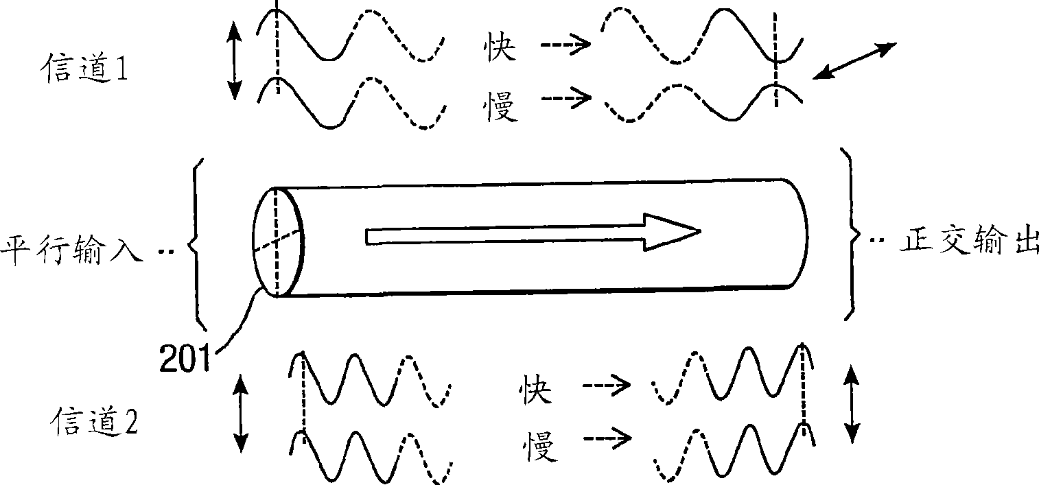
[0038] As shown, multiple channel sources 101 in each band provide parallel polarized source signals which are multiplexed together by a polarization maintaining multiplexer 102 to provide polarized WMD signals. The polarized signal then passes through differential group delay element 103 so that the WMD signal is depolarized while the time-averaged degree of polarization of each channel in the wavelength division multiplexed signal remains sufficiently large.

[0039] The depolarized WMD signals from each band are then combined by another multiplexer 104 . The multiplexed signal passes through ma...


PUM


Abstract

The present invention provides a device and method for depolarising the total field of a wavelength division multiplexed (WDM) signal. A polarisation maintaining multiplexor combines a plurality of optical signals to form a polarised multiplexed signal. The multiplexed signal is then passed through a differential group delay (DGD) element adapted to modify the polarisation state of one or more optical source signals within the multiplexed signal and thereby to at least partially depolarise the multiplexed signal.

Description

technical field [0001] The present invention relates to wavelength division multiplexing (WDM) sources, and more particularly to their use in ultra long haul (ULH) communication systems. Background technique [0002] A wavelength division multiplexed signal typically contains many channels of data, which are optical signals that are modulated in a manner to carry information. Each data channel carries independent information, but nonlinear effects in common transmission media can cause interference between these channels. These effects include four-wave mixing (FWM) and cross-phase modulation (XPM). FWM is a nonlinear effect that can occur when two or more signals of different frequencies pass through an optical fiber, which has the effect of generating a new frequency signal. These nonlinear effects interfere with the signal, limiting the effectiveness of the WDM signal in transferring data from the transmitter to the receiver. Furthermore, these nonlinear effects become...

Claims


Application Information

Patent Timeline
Patent Type & Authority Applications(China)
IPC IPC(8): H04B10/135H04B10/155H04J14/02H04B10/2507H04B10/50
CPCH04B10/506H04B10/2572G02B6/2786G02B6/278G02B6/274H04J14/02
Inventor S·德斯布鲁雷斯R·奥博兰德S·巴纳斯S·M·韦伯
Owner X TRILLION COMM CO LTD
Learn More