Technique for proportioning different materials in steel plant

A technology for iron and steel plants and materials, which is applied in the production of metal pellets, sintered ore in the iron and steel industry, and pelletized ore fields. It can solve the problems of long batching belt, serious dust, and large dust on the batching belt to achieve shortened length and flexible process layout. , Strengthen the effect of dust control

Inactive Publication Date: 2010-06-02
LAIWU IRON & STEEL GRP
View PDF0 Cites 0 Cited by
  • Summary
  • Abstract
  • Description
  • Claims
  • Application Information

AI Technical Summary

Problems solved by technology

[0004] (1) In the direct reduction process of the rotary hearth furnace for dust treatment in iron and steel enterprises, in order to ensure stable product quality and performance, the dust generated in each process must be added separately. There are as many as 5 to 10 types of dust. If you consider the spare silo , the process layout of these silos lined up will be very long, the batching belt is very long, and the plant construction is also very long, which not only causes excessive resistance to the operation of the batching belt, but also has strict requirements for the site selection of the factory area (long strips are required site); no matter where there is a problem in the batching transmission system, the entire system will be unusable, reducing the operating rate of the batching system
[0005] (2) The material properties of dust, dust sludge and auxiliary raw materials (such as coal powder, binder, etc.) produced by various processes of iron and steel enterprises are different, such as blast furnace dry dust removal ash, converter dry dust fine ash, converter environment dust removal ash The finer particle size of -200 mesh accounts for more than 80% of the dust removal dust of the coking part and the coking part, and problems such as dust raising and difficulty in adding water are easy to occur during the mixing process; while the sludge materials such as converter sludge and rolling line sludge have large water content and need to be placed for a long time Too long and easy to agglomerate
Adding to the batching belt will cause a lot of dust on the batching belt and it is difficult to control. The general solution is to mix the wet material first and then the dry material. However, the dust is still serious and difficult to be effectively controlled

Method used


Image

  • Technique for proportioning different materials in steel plant
  • Technique for proportioning different materials in steel plant

Examples


Embodiment 1

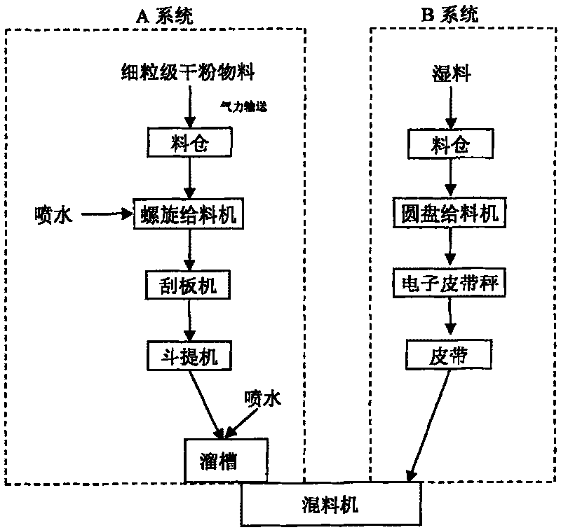
[0017] Embodiment 1. Batching technology of different performance materials in iron and steel plant

[0018] The batching system adopts two sets of systems A and B, of which the A system is used to transport blast furnace gas ash, blast furnace environmental dedusting ash, converter fine ash, converter environmental dedusting ash and electric furnace ash; B system is used for transporting coal powder, fine powder after selection and Rolling line sludge. The various dry powder materials added to the batching line of the A system are measured and batched from their respective silos through the screw feeder, and the material is humidified by spraying water in the screw feeder to make the material moisture Reach 2~6%wt; the material from the screw feeder enters the airtight scraper machine, is conveyed by the scraper machine to the bucket elevator, and then enters the mixer through the bucket elevator, and is used in the chute before entering the mixer. The material is humidified...

Embodiment 2

[0019] Embodiment 2. As described in embodiment 1, the difference is:

[0020] The batching system adopts two systems, A and B, of which system A is used for conveying blast furnace gas ash, coking dedusting ash, converter fine ash, converter environment dedusting ash and electric furnace ash; system B is used for conveying rolling line sludge and rolling steel sheet (auxiliary ). The two systems are placed in parallel, and after the calculation of the ingredients, the two systems send various raw materials to the mixer according to the fixed ratio. Among them, the powder in system A is easy to generate secondary dust, and the dry dust is pumped from the closed pneumatic tanker into the silo by means of pneumatic conveying, and a dust collector is installed on the top of the silo; at the same time, the length of the plant can be shortened by 50%, and the width can be widened by 50%. %.

Embodiment 3

[0021] Embodiment 3. As described in embodiment 1, the difference is:

[0022] The batching system adopts two systems, A and B, of which system A is used to transport coking dust, blast furnace environment dust, converter fine ash, converter environment dust and electric furnace ash; system B is used to transport coal powder, rolled steel sheet and rolling line sludge. The two sets of systems are placed vertically. After calculating the ingredients, the two sets of systems send various raw materials to the mixer according to the fixed ratio. Among them, the powder in system A is easy to generate secondary dust, and the dry dust is pumped from the closed pneumatic tanker into the silo by means of pneumatic conveying, and a dust collector is installed on the top of the silo; at the same time, the factory length design does not require a square space, and two 90 °The bar-shaped site.


PUM


Abstract

The invention relates to a technique for proportioning different materials in a steel plant. A proportioning room adopts a set of system A and a set of system B to proportion, wherein, the A system ismainly used for adding fine dry mash such as ferriferous dust; and the B system is mainly used for adding wet materials with less 13% water, or wet materials and auxiliary raw materials such as powder coal. The invention thoroughly solves the problem of dust dispersion in the proportioning process due to the dust with different properties, and the device layout of a workshop is more flexible simultaneously.

Description

technical field [0001] The invention belongs to the technical field of production of sintered ore, pellet ore and metallized pellets in the iron and steel industry, and in particular relates to a compounding technology for processing materials with different properties in iron and steel plants. Background technique [0002] Iron and steel enterprises, such as sintering plants or other dust processing plants, generally use raw material mixing systems: several high-level silos are arranged in a row (each silo contains only one raw material), and raw materials are fed from the silo through a disc. Machine or screw feeder, spread evenly on a movable batching belt in proportion, and the end of the belt sends the mixed material to the mixing system, that is, different materials are sent to the mixing device for mixing. [0003] There are following deficiencies in such commonly used raw material matching technology: [0004] (1) In the direct reduction process of the rotary hearth...

Claims


Application Information

Patent Timeline
Patent Type & Authority Patents(China)
IPC IPC(8): C22B1/00
Inventor 曾晖薛庆国李建云王静松郭强佘雪峰霍天喜罗霞光
Owner LAIWU IRON & STEEL GRP
Why Eureka
Try Eureka