
Apparatus and method for measuring medium thermal light coefficient and thermal expansion coefficient

A technology of thermal expansion coefficient and thermo-optic coefficient, applied in the field of optical measurement, can solve the problems of high mechanical precision requirements of measuring instruments, complicated calculation process, and difficult operation of sample temperature.

Inactive Publication Date: 2009-05-27
NINGBO UNIV
View PDF0 Cites 5 Cited by
  • Summary
  • Abstract
  • Description
  • Claims
  • Application Information

AI Technical Summary

Problems solved by technology

However, these measurement methods have some disadvantages. For example, if Abbe refractometer is used for measurement, the medium to be measured must be placed in a certain liquid material, and the refractive index of the liquid material must be kept between the refractive index of the medium to be measured and that of the prism. Between the refractive index, this condition limits the maximum refractive index of the medium to be measured that can be measured by the Abbe refractometer in the experiment to 1.81; the measurement method based on the principle of ellipsometry is relatively simple, but the calculation process is complicated and difficult to obtain from The measurement value directly obtains the thermo-optic coefficient of the medium; the prism coupling measurement method is based on the transmission characteristics of light in the dielectric waveguide, and requires very accurate angle measurement during the measurement process, and the angle error directly affects the measurement accuracy, so the mechanical precision of the measuring instrument In addition, the temperature control of the sample is not easy to operate
For the measurement of the coefficient of thermal expansion of materials, at present, most of the contact measurement methods using resistance coil heating are used. For example, the material is made into a rod with a length of about 0.5-1.0m, heated in a constant temperature electric furnace, and then the tiny elongation of the rod is measured to obtain The coefficient of thermal expansion of the material, obviously this method has great limitations

Method used


Image

  • Apparatus and method for measuring medium thermal light coefficient and thermal expansion coefficient
  • Apparatus and method for measuring medium thermal light coefficient and thermal expansion coefficient
  • Apparatus and method for measuring medium thermal light coefficient and thermal expansion coefficient

Examples


Embodiment Construction

[0037] The present invention will be described in further detail below in conjunction with the embodiments of the drawings.

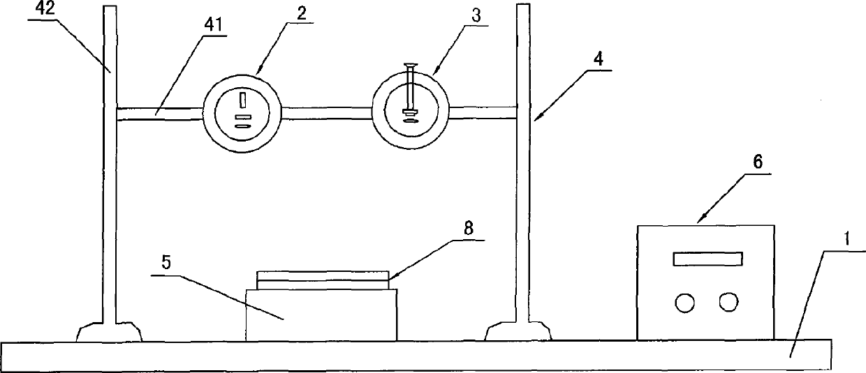
[0038] Such as figure 1 As shown, a device for measuring the thermo-optical coefficient and thermal expansion coefficient of a medium includes a base 1, a light source assembly 2 and a fringe observation assembly 3. The base 1 is provided with a support 4, a hollow sample stage 5 made of metal material, Heating device 7 (such as Figure 5a Shown) and temperature measuring device 6.

[0039] The bracket 4 is fixedly connected to the base 1. The bracket 4 includes a horizontal bracket 41 and two vertical brackets 42. One end of the horizontal bracket 41 is connected with one of the vertical brackets 42, and the other end of the horizontal bracket 41 is connected with the other vertical bracket 42. The light source assembly 2 and the fringe observation assembly 3 are movably connected to the horizontal support 41, and the light source assembly 2 and the fring...


PUM


Abstract

The invention discloses a device and method for measuring thermo-optic coefficient and thermal-expansion coefficient of medium. The device comprises a base, a light source assembly, and a fringe observation assembly, wherein, the base is provided with a support, a hollow sample stage made of metal materials, a heating device, and a temperature measuring device, the light source assembly and the fringe observation assembly are movably connected on the support, the sample is placed on the sample stage, the heating device comprises a power supply, a thermostatic controller, and an electric heater, the electric heater is disposed in the sample stage, and the temperature measuring device is respectively connected to the sample stage and the thermostatic controller. An angle desired can be set by rotating the first and the second screws, the movable light source assembly can cause the light emitted from the light source to illuminate the medium film, the movable fringe observation assembly is used to observe the whole interference fringe, and the heater is used to heating the sample, thus, the thermo-optic coefficient and the thermal-expansion coefficient of medium can be measured by observing the number of the interference fringes which pass the fixed position at different temperatures. In addition, the device has simple structure and the high measuring accuracy.

Description

Technical field [0001] The invention relates to an optical measurement technology, in particular to a device and a method for measuring the thermo-optical coefficient and thermal expansion coefficient of a medium. Background technique [0002] The thermo-optic effect refers to the phenomenon that the refractive index of the medium changes with the change of temperature; the thermal expansion effect refers to the phenomenon that the volume of the medium changes with the change of temperature. The thermo-optic effect has a wide range of applications. For example, the thermo-optic effect optical switch is an optical switch technology that has been studied more and has high application value. Compared with mechanical optical switches, thermo-optical optical switches have the advantages of good stability, small size, easy integration, etc., and are suitable for mass production. It can be predicted that with the development of all-optical networks and the application requirements of OA...

Claims


Application Information

Patent Timeline
IPC IPC(8): G01N21/45G01N25/16
Inventor 周骏马佑桥丁海芳马伟涛冯亚萍刘晓
Owner NINGBO UNIV
Learn More