Assembly bend claw mould of cylindrical roller bearing stamping retainer

A cage and bending claw technology, applied in the direction of bearing components, shafts and bearings, mechanical equipment, etc., can solve the problems of rollers not locking, affecting the bearing rotation flexibility, stamping cages, and insufficient bearing rotation flexibility. Good swivel flexibility

Active Publication Date: 2009-05-20
WAFANGDIAN BEARING CO LTD
View PDF0 Cites 8 Cited by
  • Summary
  • Abstract
  • Description
  • Claims
  • Application Information

AI Technical Summary

Problems solved by technology

[0002] At present, the cylindrical roller bearing stamping cage is widely used in the bearing industry, and the effect is good. However, when the cage and the roller are assembled, sometimes there is a problem that the roller cannot be locked, and the rotation flexibility of the bearing in the cage is not enough.
Therefore, it is urgent to solve the problems that affect the rotation flexibility of the bearing and whether the stamped cage can lock the rollers.

Method used


Image

  • Assembly bend claw mould of cylindrical roller bearing stamping retainer
  • Assembly bend claw mould of cylindrical roller bearing stamping retainer
  • Assembly bend claw mould of cylindrical roller bearing stamping retainer

Examples


Embodiment Construction

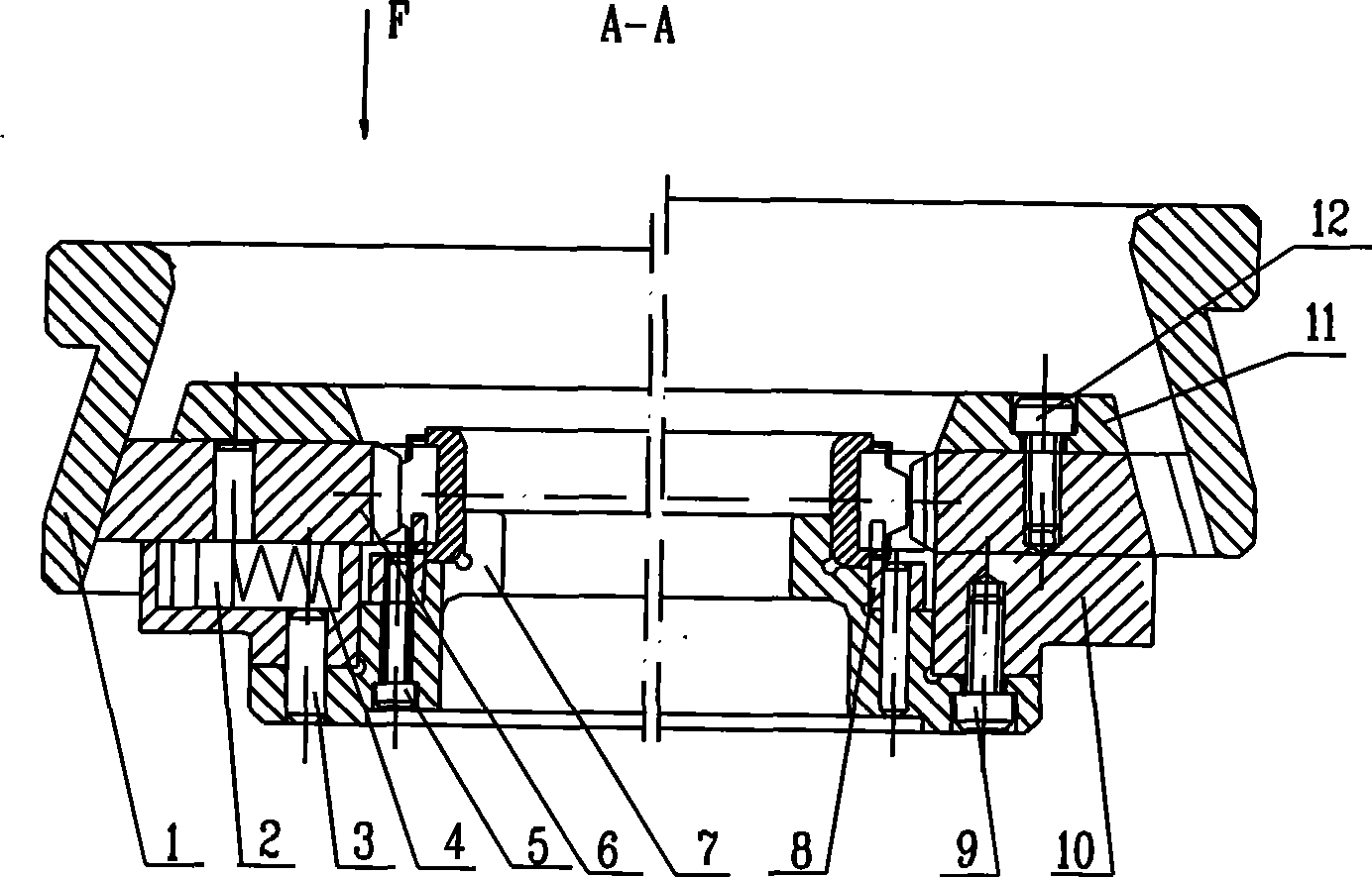
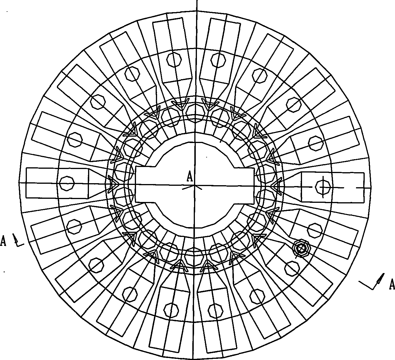
[0012] as attached figure 1 , figure 2 as shown, figure 1 The left half of the center is the working state after the force F is applied, and the right half is the original state. It consists of piece 1 taper sleeve, piece 2 pin post, piece 3 cylindrical pin, piece 4 spring, piece 5 cylindrical head socket head cap screw, piece 6 punch, piece 7 base, piece 8 locator, piece 9 cylindrical head socket head angle screw , Part 10 guide frame, part 11 cover plate, part 12 cylindrical head cap screws. The guide frame 10 and the cover plate 11 are connected by cylindrical head socket head cap screws 12, the punches 6 are connected by the pins 2 and evenly distributed on the circumference of the guide frame 10, and the pins 2 can also block the spring 4, the base 7, the locator 8 is connected by cylindrical head socket head cap screws 5, the locator 8 can evenly distribute and position the rollers, the spring 4 is installed in the groove of the locator 8 under the compression of the...


PUM


Abstract

The invention discloses an assembly bent-claw mold for cylindrical roller bearing stamping cages, which consists of a taper sleeve pin pillar, a cylindrical pin, a spring, a cylindrical-head inner hexagon screw, punches, a base, a positioner, a cylindrical-head inner hexagon screw, a guide frame, a cover plate and a cylindrical-head inner hexagon screw, wherein the guide frame and the cover plate are connected through the cylindrical-head inner hexagon screw; the punches are connected with the guide frame through the pin pillar and are uniformly distributed on the circumference of the guide frame; the spring is limited by the pin pillar; the base and the positioner are connected through the cylindrical-head inner hexagon screw; and the spring is arranged in a positioner groove under the compression of the pin pillar. The bent-claw mold has the advantages that the bent-claw mold can press uniformly distributed bent claws on the outer circumference of a cage once and for all, so as to lock rollers and ensure good revolution flexibility of bearings.

Description

Technical field [0001] The invention belongs to the technical field of bearing technology and equipment, in particular to a curved claw mold for assembling a stamping cage of a cylindrical roller bearing. Background technique [0002] At present, the cylindrical roller bearing stamping cage is widely used in the bearing industry, and the effect is good. However, when the cage and the roller are assembled, sometimes there is a problem that the roller cannot be locked, and the rotation flexibility of the bearing in the cage is not enough. . Therefore, it is urgent to solve the problems affecting the rotation flexibility of the bearing and whether the stamped cage can lock the rollers. Contents of the invention [0003] In order to improve the rotation flexibility of the bearing and the stamping cage can lock the rollers, the invention proposes a curved claw mold for cylindrical roller bearing stamping cage assembly. Next, the outer diameter of the cage can be pressed into ...

Claims


Application Information

Patent Timeline
IPC IPC(8): F16C33/46F16C43/04
Inventor 周建美李爱君何东生
Owner WAFANGDIAN BEARING CO LTD
Why Eureka
Try Eureka