
Analysis method used for in-mold decoration injection molding

A technology of injection molding and in-mold decoration, applied in the field of analysis, can solve problems such as unreasonable assumptions, inability to meet user needs, etc., to reduce costs, improve analysis accuracy, and shorten development time.

Inactive Publication Date: 2009-05-13
NAT CHIN YI UNIV TECH
View PDF0 Cites 6 Cited by
  • Summary
  • Abstract
  • Description
  • Claims
  • Application Information

AI Technical Summary

Problems solved by technology

[0010] One of the main difficulties in the simulation of the injection molding process is the instantaneous free surface of the molten resin. When the in-mold decoration injection molding integrates processing technologies such as flat printing, thermocompression molding, precision punching and injection molding, the moldable film must be overcome during the injection process. Problems such as positioning, ink scouring, stretching and warping, etc., the application of computer-aided engineering analysis technology can help to understand the cause of the problem, but there are still too many unreasonable applications of commercial computer-aided engineering technology in the injection molding process of in-mold decoration Assumptions
Therefore, the habitual user cannot meet the needs of the user in actual use

Method used


Image

  • Analysis method used for in-mold decoration injection molding
  • Analysis method used for in-mold decoration injection molding
  • Analysis method used for in-mold decoration injection molding

Examples


Embodiment

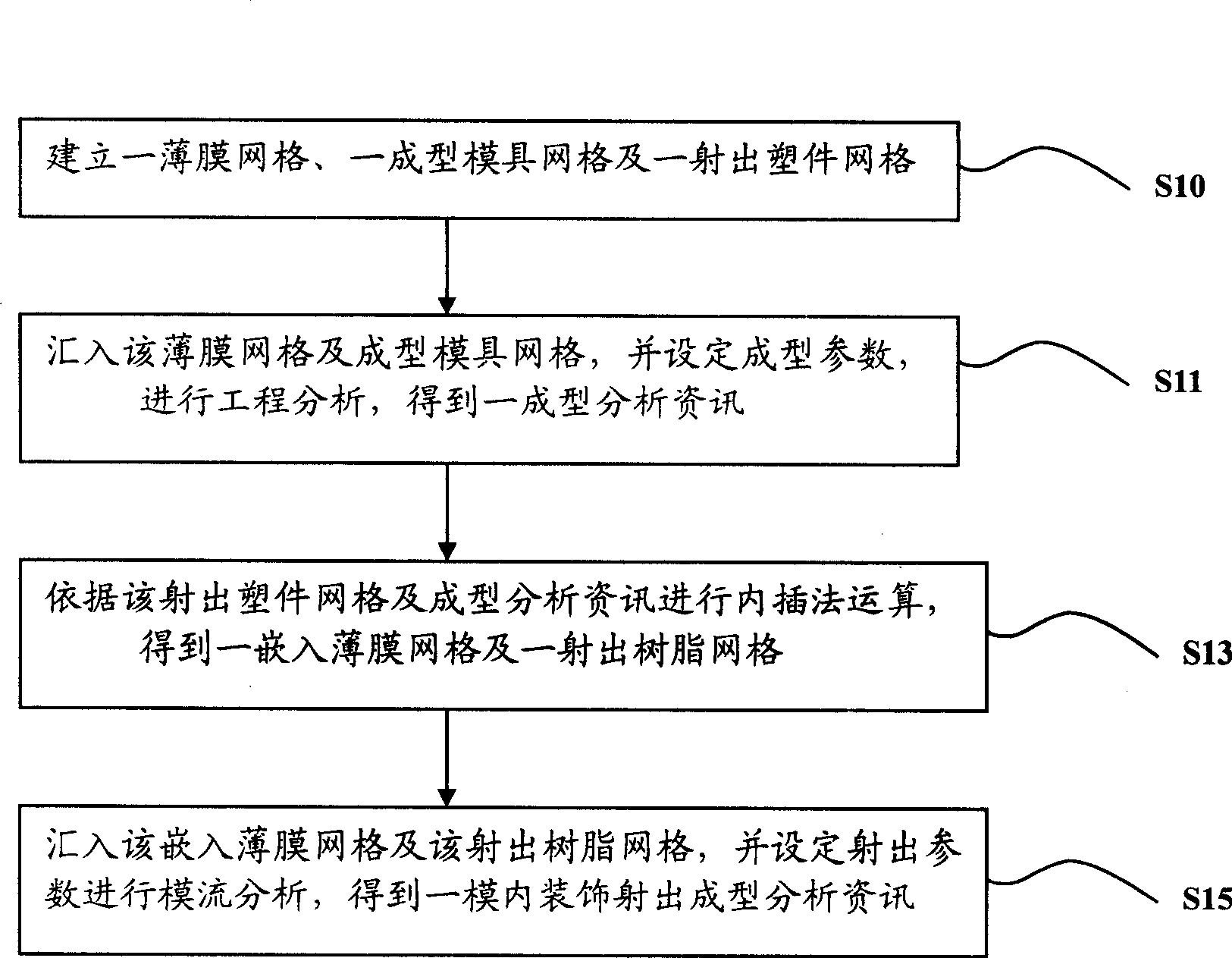
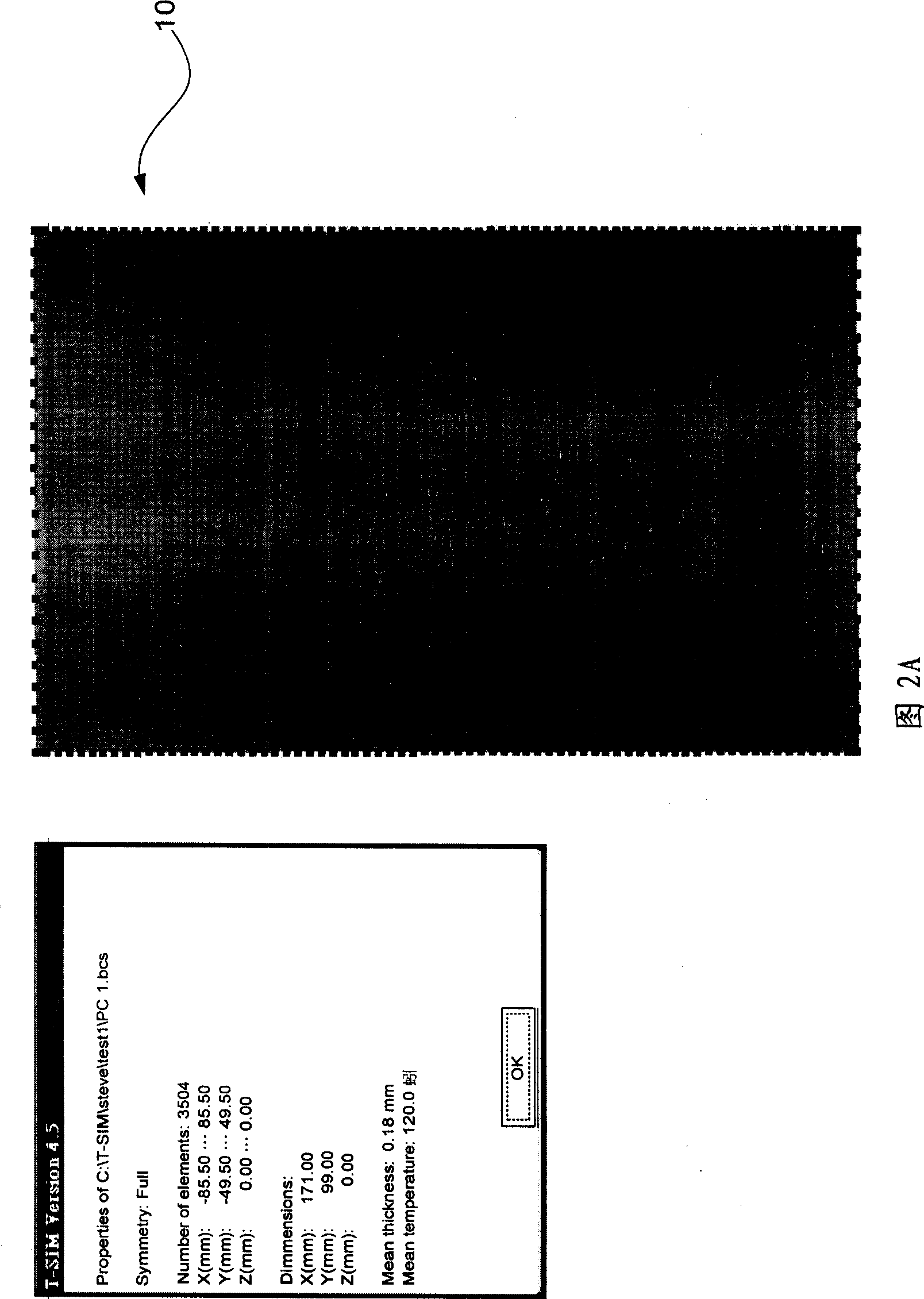
[0071] This embodiment is the implementation process of actually using the engineering analysis method of the present invention, please refer to figure 1 , execute step S10 first, establish a film grid 10, a forming mold grid 12 and a plastic part grid 14, the above-mentioned film grid 10 is to utilize T-SIM software to establish, please refer to Fig. 2A, it is the present embodiment Schematic diagram of the film grid, and the size of the film grid in this embodiment is 170mm X 100mm, and the thickness is 0.175mm.

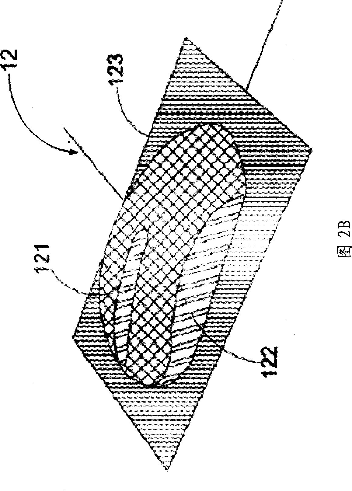
[0072] The forming mold grid 12 of this embodiment requires good grid quality, and is established using Moldex3D-Mesh software, and controls the appropriate number and quality of grids. The format of the forming mold grid 12 is selected from rapid manufacturing (STL) format) for T-SIM software to read, the forming mold grid 12 is shown in Figure 2B, the area marked 121 is the cut and formed film area (formable film area), and the area marked 122 is In the trimming...


PUM

PropertyMeasurementUnit
thicknessaaaaaaaaaa

Abstract

The invention relates to an engineering analysis method used for in-mold decoration injection molding. The method is divided to molding engineering analysis, grid interface processing and injection engineering analysis, and comprises the following steps: first, establishing a film grid, a molding mould grid and an injection molding grid, importing the film grid and the molding mould grid, and setting a molding parameter for engineering analysis so as to obtain molding analysis information; operating according to the injection molding grid and the molding analysis information to obtain an embedded film grid and an injection resin grid; and importing the embedded film grid and the injection resin grid, and setting an injection parameter for mold flow analysis so as to obtain in-mold decoration analysis information. The engineering analysis method is integrated with a molding analysis program and an injection analysis program, improves the analysis precision of the in-mold decoration injection molding, and shortens the engineering analysis time of the in-mold decoration injection molding, thereby shortening development time of a product and reducing cost.

Description

Technical field: [0001] The invention relates to an analysis method, in particular to an engineering analysis method for in-mold decoration injection molding. Background technique: [0002] At present, the plastic injection molding process is the most important discipline in the contemporary polymer processing procedures. Because the process has the advantages of easy molding of plastic parts, mass production, low production cost and suitable for complex molding, it is widely used in consumer goods and information appliances. , electronic communications and automobile and motorcycle components, has become the most widely used technology in polymer processing procedures. [0003] For Taiwan, China, the mold industry ranks fourth in the world, among which plastic injection molds are the most important. With the improvement of new materials, production technology and equipment, and even new products are changing with each passing day, and they are listed on the market at an ext...

Claims


Application Information

Patent Timeline
Patent Type & Authority Applications(China)
IPC IPC(8): G06F17/50
Inventor 邱维铭钱玉树唐兆璋
Owner NAT CHIN YI UNIV TECH
Learn More