Measuring system and method for tangential piezoelectric strain constant of piezoelectric material by quasi-static method

A technology of piezoelectric strain constant and quasi-static method, which is applied to measuring devices, measuring electrical variables, instruments, etc., can solve the problems of cumbersome piezoelectric constant testing process and poor practicability

Inactive Publication Date: 2009-05-13
INST OF ACOUSTICS CHINESE ACAD OF SCI
View PDF1 Cites 7 Cited by
  • Summary
  • Abstract
  • Description
  • Claims
  • Application Information

AI Technical Summary

Problems solved by technology

[0004] The purpose of the present invention is: to overcome the dynamic method in the past to measure the piezoelectric material d 15 The piezoelectric constant test process is cumbersome and has poor practicability. A measurement principle based on quasi-static method is provided (applying a low-frequency force to the piezoelectric sample to be tested and measuring the piezoelectric effect of the piezoelectric sample under the action of the force). The low-frequency piezoelectric charge generated to obtain its piezoelectric constant) piezoelectric material d 15 Tangential piezoelectric constant measurement system device and method, the measurement system is simple in structure, easy to operate, not only can meet the requirements of measurement accuracy, but also easy to implement and popularize

Method used


Image

  • Measuring system and method for tangential piezoelectric strain constant of piezoelectric material by quasi-static method
  • Measuring system and method for tangential piezoelectric strain constant of piezoelectric material by quasi-static method
  • Measuring system and method for tangential piezoelectric strain constant of piezoelectric material by quasi-static method

Examples


Embodiment 1

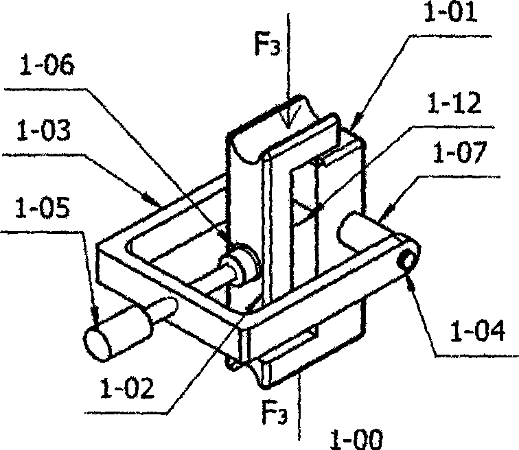
[0048] refer to figure 1 , Figure 1a and Figure 1b , to make a tangential force component 1-00 that can apply a tangential force to the piezoelectric element by applying the principle of force conversion.

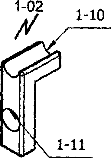
[0049]The tangential force component 1-00 in this embodiment consists of a force-pressurized fixed bracket 1-01, a force-pressurized part 1-02, a fixed frame 1-03, a fixed shaft 1-04, and an adjusting bolt 1-05 , an insulating sleeve 1-06, a first positioning bushing 1-07 and a second positioning bushing 1-08, in which the fixed bracket 1-01 under pressure and the pressure part 1-02 are both L-shaped metal Rods are made of metal materials such as duralumin, stainless steel or copper. The inner faces of the vertical rods of their respective L-shaped metal rods are the force end faces that exert force on the piezoelectric sample to be tested. It is required to be processed flat and smooth. Their respective L-shaped There are horizontal semicircular grooves 1-09 and 1-10 ...

Embodiment 2

[0051] refer to Figure 5 Build a set of piezoelectric elements d 15 The system device used in the quasi-static measurement of the tangential piezoelectric strain constant, the measurement piezoelectric element d given in this embodiment 15 The system device of the tangential piezoelectric strain constant is composed of a tangential force component 1-00, a force device 2-00 and a circuit part 3-00; wherein the tangential force component 1-00 is directly applied in Example 1 of (see figure 1 ), the force device 2-00 and the circuit part 3-00 directly select the ZJ series quasi-static d 33 Measuring instruments, such as ZJ-3, ZJ-4 series quasi-static d 33 Measuring instrument, ZJ-6 series quasi-static d 33 / d 31 Measuring instrument, or other quasi-static d 33 Measuring instruments and other products, the force applying device 2-00 mainly includes the upper test probe 2-01 and the lower test probe 2-02, the adjustment hand wheel 2-03, the upper probe 2-04 of the internal c...

Embodiment 3

[0054] Adopt measurement system provided by the present invention to measure piezoelectric element d 15 Specific method for tangential piezoelectric strain constant.

[0055] The piezoelectric measured element 1-12 in the present embodiment is a rectangular sheet made of PZT piezoelectric ceramic material, with a length of 15mm, a width of 10mm, and a thickness of 2mm (for this measurement system: for the piezoelectric measured element There are no too many restrictions on the length, width, and thickness, as long as it can be clamped in the tangential force component given in Example 1 (1-00). Prepare and polarize the polarized electrodes on two planes, then remove the original polarized electrodes, and re-prepare the measuring electrodes on two planes of 15 mm × 10 mm (the polarization and electrodes of the above-mentioned piezoelectric tested samples 1-12 process is well known in the art to measure d 15 The manufacturing process of the tangential piezoelectric constant te...


PUM

PropertyMeasurementUnit
Lengthaaaaaaaaaa
Widthaaaaaaaaaa
Thicknessaaaaaaaaaa

Abstract

The invention discloses a quasi-static measurement method for a tangential piezoelectric strain constant of a piezoelectric material d15, and a system thereof. In the method, a special tangential stressing component converts 'longitudinal force' of a piezoelectric test sample into a 'tangential force' on an existing quasi-static d33 measuring apparatus, and directly provides a measurement result of the d15 tangential piezoelectric strain constant of the piezoelectric test sample. The measurement system consists of the tangential stressing component, a force application device and a circuit component, wherein, the tangential stressing component consists of a strained compression fixing component which is composed of a strained compression fixing bracket, a fixing frame, a fixing shaft, an adjusting bolt, an insulating bush and a positioning shaft sleeve, and a strained compression component. The force application device and the circuit component are applicable to various types of quasi-static d33 measuring apparatuses, and the force application device and the circuit component of the quasi-static d33 measuring apparatus are connected by two multi-core cables according to requirements of the existing quasi-static d33 measuring apparatus. Compared with the existing dynamic method, the method and the system have the advantage of simple operation, strong practicability and easy popularization and implementation.

Description

technical field [0001] The invention relates to a method for measuring the piezoelectric constant of a piezoelectric material, in particular to a tangential piezoelectric strain constant (abbreviated as d 15 Piezoelectric constant) quasi-static measurement with force component and measurement system and method. Background technique [0002] The piezoelectric constant is an important parameter to characterize the piezoelectric properties of piezoelectric materials, mainly including d 33 Longitudinal piezoelectric strain constant, d 31 Transverse piezoelectric strain constant and d 15 Tangential piezoelectric strain constant, etc., for d 15 The measurement of the tangential piezoelectric strain constant has been carried out by dynamic method in the past (for specific methods, please refer to IEEE standard: IEEE Standard on Piezoelectricity, ANSI / IEEE Std.176-1987, national standard: GB / T3389.6-1997 piezoelectric ceramic materials Performance test method, long sheet thickne...

Claims


Application Information

Patent Timeline
IPC IPC(8): G01R29/22
Inventor 潘潮陈守六鲍小琪易晓星张童金亨焕章力旺
Owner INST OF ACOUSTICS CHINESE ACAD OF SCI
Why Eureka
Try Eureka