Refrigerant filling apparatus of refrigerating and air conditioning apparatus and refrigerant filling method of refrigerating and air conditioning apparatus
A technology of an air-conditioning device and a filling method, which is applied in the directions of refrigerants, refrigerators, refrigeration components, etc.
- Summary
- Abstract
- Description
- Claims
- Application Information
AI Technical Summary
Problems solved by technology
Method used
Image

Examples
Embodiment approach 1
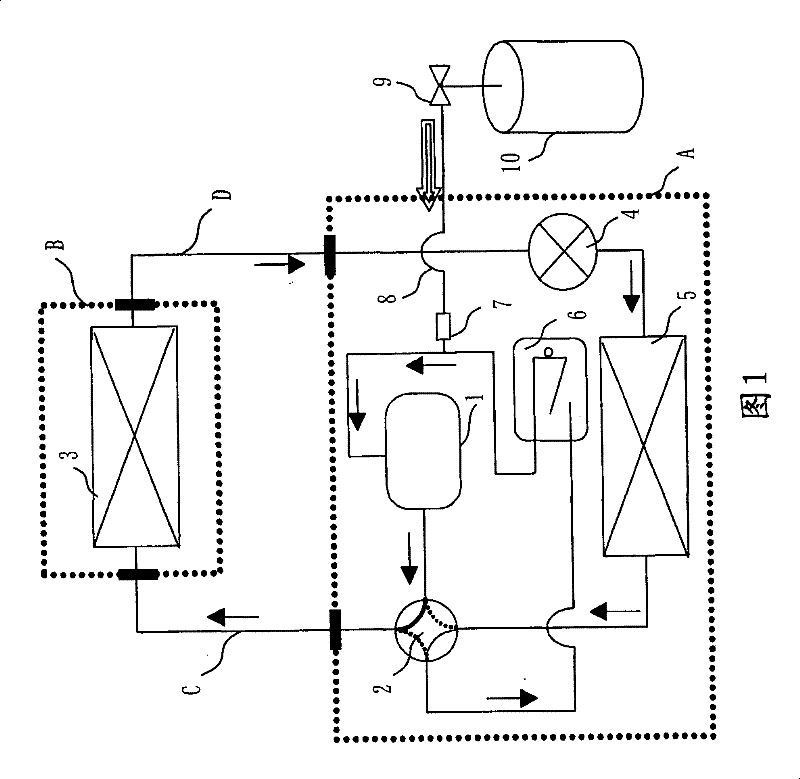
[0068] Hereinafter, an air conditioner as an example of a refrigerating and air-conditioning apparatus will be described as an example. As the refrigerating and air-conditioning apparatus, there are, for example, refrigerators and the like in addition to air conditioners.
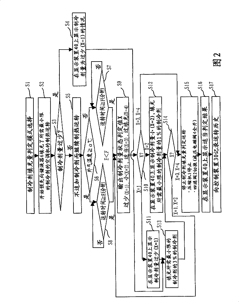
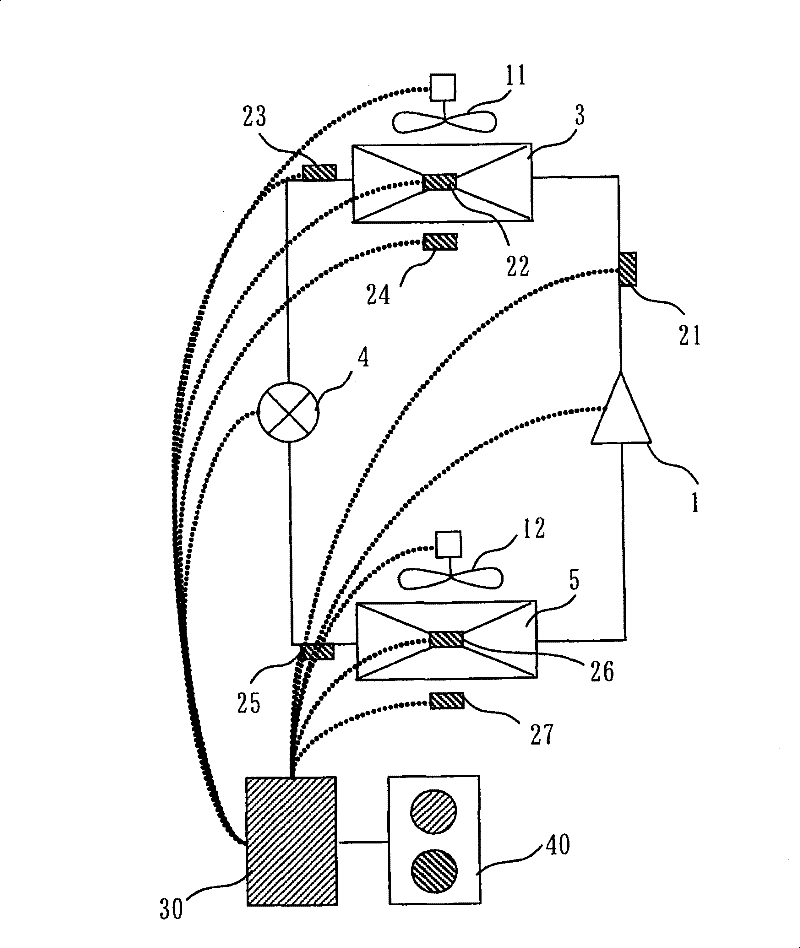
[0069] Figure 1 to Figure 8 is a diagram showing Embodiment 1, figure 1 It is a refrigerant circuit diagram at the time of refrigerant charging of the air conditioner, figure 2 A refrigerant filling flowchart showing a refrigerant filling method, image 3 It is a diagram showing the control object of the control device 30 when the refrigerant charging amount judging operation mode is selected, Figure 4 It is a graph showing the relationship between the outside air temperature and the time until the refrigeration cycle stabilizes, Figure 5 It is a figure which shows the control method of the rotation speed of the compressor 1 at the time of refrigerant charging, Figure 6 It is a figure showing the...
Embodiment approach 2
[0144] Figure 9 It is a figure which shows Embodiment 2, and is a refrigerant circuit diagram at the time of refrigerant charging of an air conditioner. and figure 1 The difference is that the decompression solenoid valve 4 is built in the indoor unit B side.
[0145] In the case where the pressure reducing solenoid valve 4 is built in the indoor unit B, by following Figure 9 Circulating in the refrigerant circuit in the direction of the arrow, the same refrigerant charging method as that shown in Embodiment 1 can be realized. That is, in order to grasp the state of the refrigerant quantity, it is shown that when the decompression solenoid valve 4 is located on the side of the outdoor unit A, it is necessary to perform a heating operation, and when it is located on the side of the indoor unit B, it is necessary to perform a cooling operation.
[0146] Among them, the section on the refrigerant circuit where the density of the refrigerant is the highest, that is, the refr...
Embodiment approach 3
[0148] On the other hand, even with figure 1 The same refrigerant circuit, and has an automatic control valve 15 that can realize opening and closing between the refrigerant cylinder 10 and the refrigeration circuit, such as Figure 10 The above-mentioned operation method can also be used for the refrigerant charging method as shown.
[0149] Figure 10 It is a figure which shows Embodiment 3, and is a refrigerant circuit diagram at the time of refrigerant charging of an air conditioner.
[0150] In the refrigerant filling method of the present invention, when it is judged that the amount of refrigerant is appropriate, the heating operation mode is stopped, the four-way valve 2 is switched while the compressor 1 is stopped, and furthermore, by setting the decompression solenoid valve 4 to full Open, thereby eliminating the pressure difference in the refrigerant circuit due to the heating operation, and as a result, excessive refrigerant filling in the future is suppressed. ...
PUM
 Abstract
Description
Claims
Application Information
 - Generate Ideas
- Intellectual Property
- Life Sciences
- Materials
- Tech Scout
- Unparalleled Data Quality
- Higher Quality Content
- 60% Fewer Hallucinations
Browse by: Latest US Patents, China's latest patents, Technical Efficacy Thesaurus, Application Domain, Technology Topic, Popular Technical Reports.
© 2025 PatSnap. All rights reserved.Legal|Privacy policy|Modern Slavery Act Transparency Statement|Sitemap|About US| Contact US: help@patsnap.com