
Wire-cutting device for sewing machine

A technology of cutting device and sewing machine, which is applied in the sewing machine to cut off the thread mechanism, sewing machine components, sewing machine loop mechanism, etc., and can solve the problem of catching upper thread and so on

Inactive Publication Date: 2009-05-06
YAMATO SEWING MASCH MFG CO LTD
View PDF8 Cites 11 Cited by
  • Summary
  • Abstract
  • Description
  • Claims
  • Application Information

AI Technical Summary

Problems solved by technology

Therefore, when the movable blade enters, the above-mentioned movable blade may come into contact with one of the lower surface of the needle jack and the upper surface of the looper, or the yarn hooking portion of the movable blade cannot reliably catch the surface. line condition

Method used


Image

  • Wire-cutting device for sewing machine
  • Wire-cutting device for sewing machine
  • Wire-cutting device for sewing machine

Examples


Embodiment Construction

[0023] Preferred embodiments of the present invention will be described in detail below with reference to the accompanying drawings.

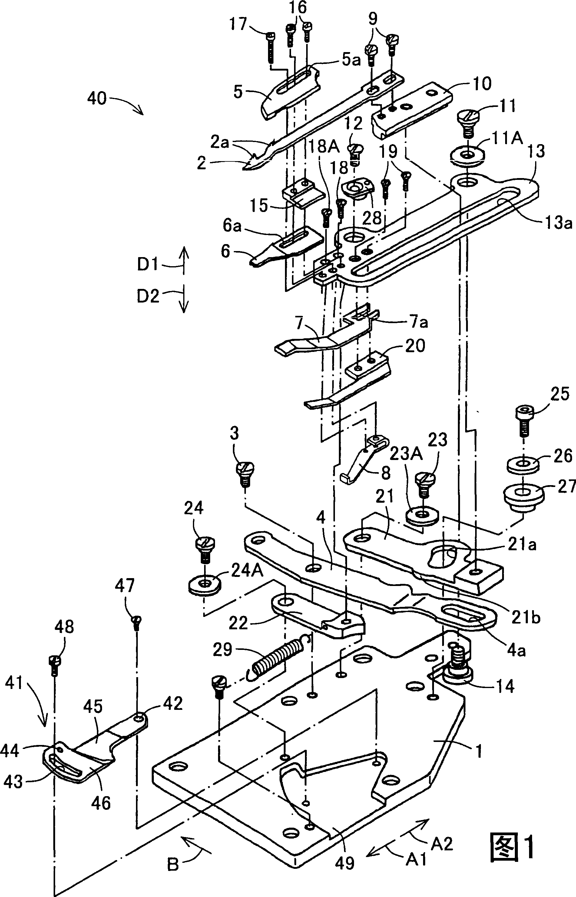
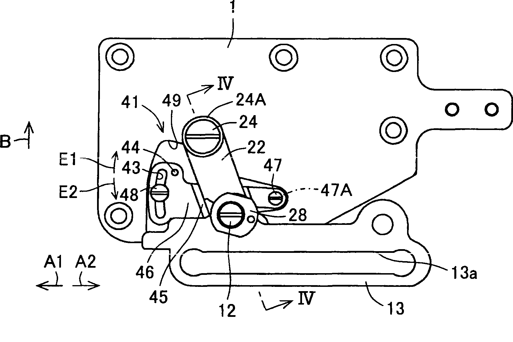
[0024] Fig. 1 is an exploded perspective view of a yarn cutting device 40 of a sewing machine according to an embodiment of the present invention, figure 2 It is a plan view of the yarn cutting device 40 with some components omitted. In the base of the double circular stitch sewing machine or the flat stitch sewing machine, viewed from the side of the sewing operator, there is arranged below the needle jack plate (not shown in the figure) with the needle drop portion 31, which is depicted as a circular movement track in plan view. 32 (refer to the Figure 10 ) the looper 33 that swings along the forward direction A1 and the backward direction A2, on the downstream side ( figure 2 Above), the yarn cutting device 40 of this embodiment is installed.

[0025] The above-mentioned yarn cutting device 40 includes a movable blade 2 , a driving rod 4...


PUM


Abstract

The present invention provides a yarn cutting device of sewing machine, which can authentically capture an upper thread coil with a movable blade for cutting off. The height position of a blade holding base (13) which holds a movable blade (2), a fixed blade (5) and a yarn clamping plate (7) in the up-and-down direction can be adjusted with a height adjusting part (41). The height of the blade holding base (13) is adjusted with the height adjusting part (41) so that the movable blade which is adjacent with the entering positions of needle supporting plate and curved needle and enters from a narrow space between the lower surface of needle supporting plate and upper surface of curved needle is configured to a position that does not contact a random surface selected from the lower surface of needle supporting plate and upper surface of curved needle. The upper thread coil is caught authentically by a yarn hooking part of movable blade (2) for being cut off.

Description

technical field [0001] The present invention relates to a method for cutting the upper thread and sewing bottom thread (ルパパ ) The yarn cutting device of the sewing machine. Background technique [0002] The yarn cutting device of the sewing machine in the prior art has a movable blade, a driving rod, a fixed blade and a tension plate. Part enters between the forward position and the backward position between the needle jack plate and the looper to reciprocate; the driving rod makes the movable blade reciprocate between the above-mentioned forward position and the backward position; the fixed blade when sewing When the above-mentioned movable blade moves from the forward position to the backward position after the action is completed, the upper thread and the stitching bottom thread captured by the above-mentioned yarn catching part are cut off in cooperation with the above-mentioned movable blade; The ends of the upper thread and the lower sewing thread are elastically pr...

Claims


Application Information

Patent Timeline
IPC IPC(8): D05B65/00
CPCD05B51/00D05B63/02D05B65/02D05B65/06
Inventor 桥本诚治弥永明夫
Owner YAMATO SEWING MASCH MFG CO LTD
Learn More