
Energy accumulation device for fly wheel

A flywheel energy storage and flywheel technology, which is applied in electromechanical devices, control mechanical energy, bearings, etc., can solve the problems of low rigidity and bearing capacity of magnetic bearings of the same diameter, expensive structure of superconducting magnetic levitation technology, and large friction loss of mechanical rolling bearings. Fast synchronization of charging and discharging, simple structure, and the effect of reducing frictional power consumption

Inactive Publication Date: 2009-04-29
SOUTHEAST UNIV
View PDF0 Cites 20 Cited by
  • Summary
  • Abstract
  • Description
  • Claims
  • Application Information

AI Technical Summary

Problems solved by technology

Its disadvantages are: the magnetic bearing and its measurement and control system are more complicated, and the cost is much higher than that of traditional mechanical bearings; the stiffness and load capacity of magnetic bearings with the same diameter are also much smaller than traditional mechanical bearings
The superconducting magnetic levitation technology needs to construct a relatively expensive high and low temperature environment
At present, magnetic suspension bearings have been applied in flywheel energy storage internationally, but mass production has not yet been seen; domestic magnetic suspension bearings have problems such as relatively small stiffness and low reliability, and their application in flywheel energy storage is still in the experimental stage Chamber stage; mechanical rolling bearings have high friction loss and low service life

Method used


Image

  • Energy accumulation device for fly wheel

Examples


Embodiment 1

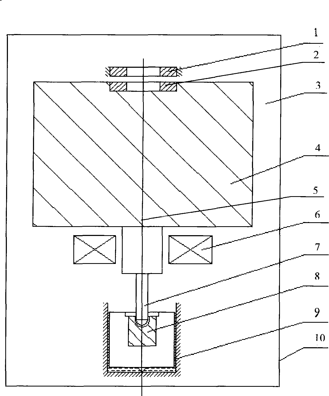
[0021] A flywheel energy storage device, comprising a casing 10, the interior of the casing 10 is a vacuum chamber 3, a flywheel body 4 made of high-strength steel is arranged in the vacuum chamber 3, and a small elastic shaft 7 passes through the lower end of the flywheel shaft 5 A pivot thrust bearing 8 coaxial with the flywheel body 4 is connected, and an oil film damper 9 is arranged outside the pivot thrust bearing 8; a motor 6 is coaxially arranged between the flywheel body 4 and the small elastic shaft 7, The flywheel shaft 5 is integrated with the rotor of the motor 6, and the upper end surface of the flywheel body 4 is provided with a permanent magnet bearing lower magnetic ring 2 coaxial with the flywheel body 4, and directly above the permanent magnetic bearing lower magnetic ring 2 is provided with a The upper magnetic ring 1 of the permanent magnetic bearing, and the attraction between the upper magnetic ring 1 of the permanent magnetic bearing and the lower magnet...


PUM


Abstract

The invention provides a high-efficient flywheel energy storage device, comprising a shell, a motor arranged in the cavity of the shell, a flywheel and a support structure, wherein, the cavity is vacuumized; the motor is arranged under the flywheel; a flywheel shaft of the flywheel and a rotor of the motor are integrated into a whole; the support structure is formed by mixing a pivot thrust bearing and a permanent magnetic bearing. The device of the invention has the advantages of simple structure, convenient maintenance, low cost, good stability, simultaneous and quick charging and discharging and high energy storage efficiency.

Description

1. Technical field [0001] The invention relates to a novel high-efficiency flywheel energy storage device, which belongs to the technical field of electric energy conversion and storage. 2. Background technology [0002] The new type of conversion and storage of electric energy has become a hot topic in the field of energy research. Flywheel energy storage technology has outstanding advantages such as high power conversion efficiency, fast charging and discharging, not limited by geographical environment, can be scattered nearby, does not pollute the environment, has high energy storage density per unit mass, and has broad application prospects, and has attracted much attention from academic circles at home and abroad. , and may become a new technology for energy storage in the 21st century. [0003] The principle of flywheel energy storage is: through the electric / generating reciprocal motor, the mutual conversion between electric energy and the mechanical kinetic energy o...

Claims


Application Information

Patent Timeline
Patent Type & Authority Applications(China)
IPC IPC(8): H02K7/02H02K7/09F16C32/04F16C17/04H02K21/12
CPCY02E60/16F16C39/063F16C32/0417F16C2361/55
Inventor 蒋书运
Owner SOUTHEAST UNIV
Learn More