Method for producing movable contact body with protrusion

A manufacturing method and a technology for a contact body, applied in chemical instruments and methods, electronic equipment, lamination, etc., can solve the problems of shredding, difficulty in ensuring the installation stability of protruding parts, etc.

Inactive Publication Date: 2009-04-29
PANASONIC CORP
View PDF2 Cites 0 Cited by
  • Summary
  • Abstract
  • Description
  • Claims
  • Application Information

AI Technical Summary

Problems solved by technology

[0024] However, when the TPU film is simply punched into a small-diameter cylindrical protruding part, due to the high flexibility of the TPU film, when it is cut with a cutter, it will eventually feel torn, and it is often formed in the cutting direction. The state of processing where many burrs are generated on the lower end side
In this state, it is difficult to secure the mounting stability of the protruding parts, and sometimes they must be sorted and mounted

Method used


Image

  • Method for producing movable contact body with protrusion
  • Method for producing movable contact body with protrusion
  • Method for producing movable contact body with protrusion

Examples


Embodiment Construction

[0058] Below, refer to Figure 1 to Figure 18 , to describe the embodiment of the present invention. Components that are the same as those described in the prior art are denoted by the same symbols, and detailed description thereof will be omitted.

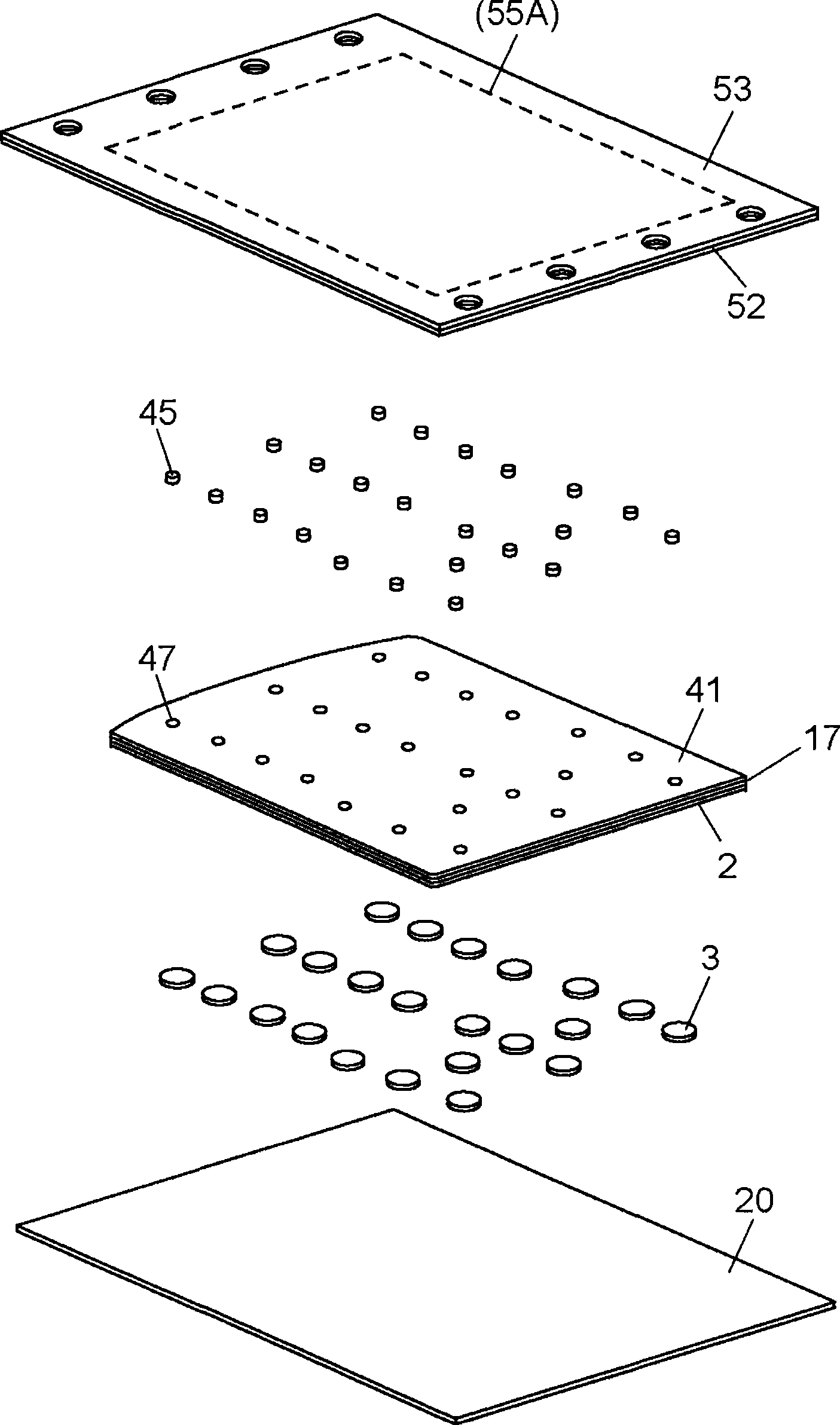
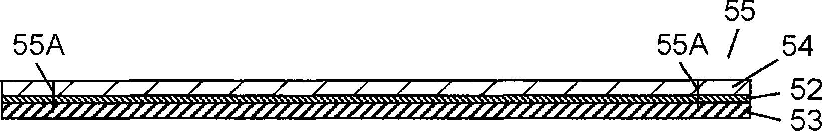
[0059] figure 1 It is a cross-sectional view of a movable contact body with a protrusion manufactured by a method of manufacturing a movable contact body with a protrusion according to an embodiment of the present invention. figure 2 yes figure 1 An exploded perspective view of the movable contact body with protrusions shown.

[0060] In the figure, a functional layer 17 constituting an EL element is stacked on the lower surface of a translucent base film 41 made of a TPU film cut into a predetermined shape. Further, on the lower surface of the functional layer 17, the movable contacts 3 are bonded and held at predetermined positions through the adhesive layer 2, respectively. At a position on the base film 41 correspondin...


PUM

PropertyMeasurementUnit
thicknessaaaaaaaaaa
thicknessaaaaaaaaaa

Abstract

The method comprises steps of forming bump members 45 by carrying out a half-cut process on first substrate 56 comprising highly flexible first plastic film 51 adhered to first reinforcing film 53 of a material having rigidity higher than first plastic film 51 with adhesive layer 52, removing first plastic film 51 in a manner to leave cut-out bump members 45 on first reinforcing film 53, adhering bump members 45 to second plastic film 61 coated with adhesive 47, and securely bonding thereafter bump members 45 to second plastic film 61 by hardening adhesive 47. Thereby, efficiently bonding bump members of a small cylindrical shape can be punched out of a highly flexible plastic film without leaving considerable extent of cutting burrs.

Description

technical field [0001] The present invention relates to a method of manufacturing a movable contact body with protrusions used in panel switches and the like for input operations of various electronic devices. Background technique [0002] In recent years, as various electronic devices have become smaller and lighter, as panel switches for input operations of the electronic devices, panel switches with thin thickness, good operation feeling and stable electrical contact have been developed. Among them, a panel switch composed of a so-called movable contact body has been frequently developed. The above-mentioned movable contact body is formed by holding a plurality of dome-shaped movable contacts made of elastic conductive metal plates on an insulating resin sheet. In addition, in order to use the above-mentioned electronic equipment well at night, etc., it is preferable that its operation buttons be illuminated, and generally, LED lighting is widely used. [0003] Hereinaf...

Claims


Application Information

Patent Timeline
Patent Type & Authority Applications(China)
IPC IPC(8): H01H11/00
CPCB32B2457/08B32B37/12H01H2229/056B32B2375/00B32B2367/00B32B2038/042B32B37/02H01H13/83H01H2215/00B32B2457/20
Inventor 唐木稔沼本信宏
Owner PANASONIC CORP
Why Eureka
Try Eureka