
Catalytic cracking oil and gas separation method

A catalytic cracking and separation method technology, which is applied in the field of catalytic cracking oil-gas separation, can solve the problems of increasing gasoline octane number and low separation precision, and achieve the effects of reducing heat source temperature, improving separation efficiency and reducing energy consumption

Active Publication Date: 2009-04-29
CHINA PETROLEUM & CHEM CORP +1
View PDF6 Cites 20 Cited by
  • Summary
  • Abstract
  • Description
  • Claims
  • Application Information

AI Technical Summary

Problems solved by technology

Part of the heavy gasoline fraction at the top of the catalytic diesel stripper returns to the main fractionator, and part of it enters the reaction-regeneration system to be cracked into lighter gasoline fractions to increase the octane number of gasoline. The disadvantage of gasoline separation in this method is that the separation of gasoline affects the main fractionator. The operation and the separation accuracy is not high because there is no overhead reflux

Method used


Image

  • Catalytic cracking oil and gas separation method
  • Catalytic cracking oil and gas separation method
  • Catalytic cracking oil and gas separation method

Examples


Embodiment

[0046] The examples illustrate the gasoline separation effect of the catalytic cracking oil-gas separation method provided by the present invention.

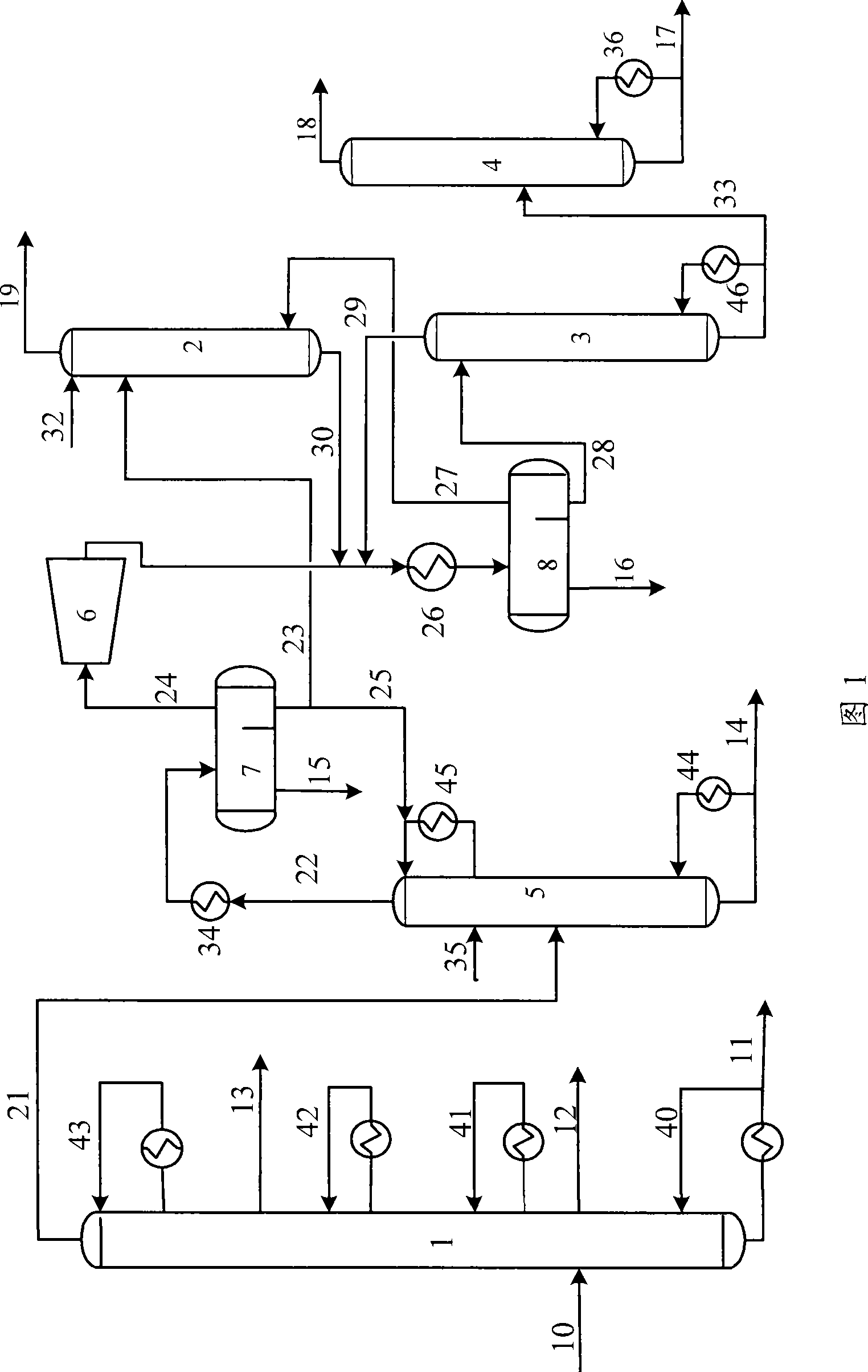
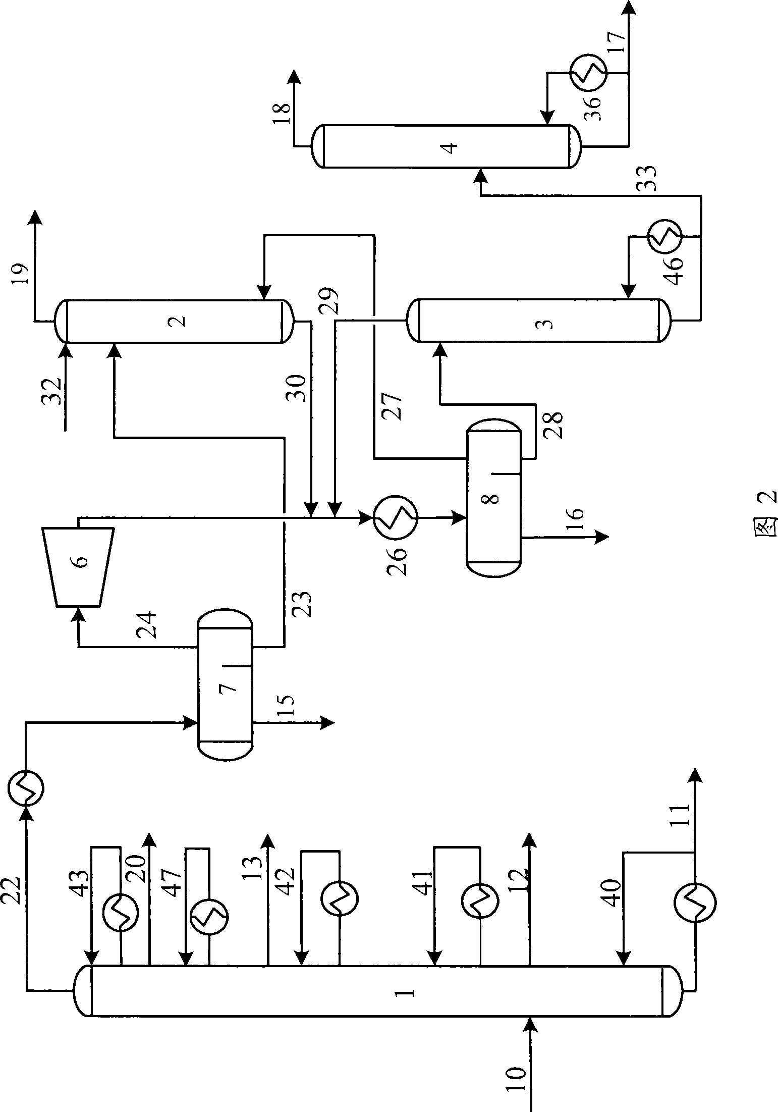
[0047] Separation of catalytic cracking reaction oil and gas according to the process shown in Figure 1, the oil and gas are introduced into the main fractionation tower, and the operation of the catalytic cracking main fractionation tower makes the top discharge be gasoline and fractions below C4, and the main fractionation tower is sequentially separated from top to bottom Diesel oil, heavy diesel oil and oil slurry; gasoline and fractions below C4 are introduced into the gasoline fractionation tower to separate heavy gasoline fractions, light gasoline and fractions below C4, and fractions below C4 are introduced into the subsequent absorption and stabilization system to separate light gasoline fractions and liquefy gas and dry gas.

[0048] The flow rate and composition of oil and gas in catalytic cracking reaction are shown ...


PUM


Abstract

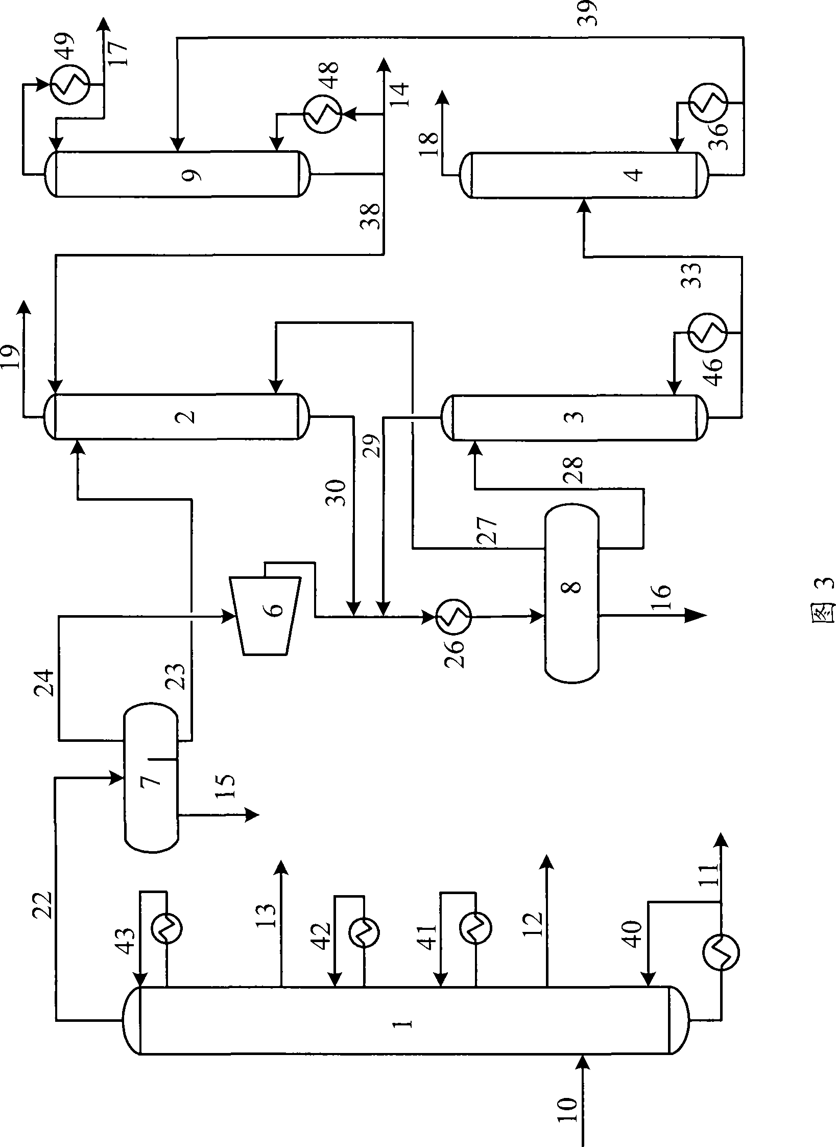
The invention discloses a method for separating catalytic cracking oil gas. The method comprises the following steps: oil gas produced by catalytic cracking reaction is introduced into a main fractionating tower; after distillation, materials discharged from a tower top are gasoline and gases with a molecular structure having less than 4 carbon atoms, and diesel, cycle oil and / or heavy diesel and slurry oil are separated sequentially by the main fractionating tower from top down; the gasoline and the gases with a molecular structure having less than 4 carbon atoms are introduced into a gasoline splitter and heavy naphtha are discharged from the bottom of the tower; light gasoline and gases with a molecular structure having less than 4 carbon atoms discharged from the top of the gasoline splitter are introduced into an FCC absorption and stabilization system to separate light gasoline light naphtha, liquid gas and dry gases. The method injects gases discharged from the tower top of the main fractionating tower into a middle part of the gasoline splitter, and arranges reflux on the top of the gasoline splitter and a reboiler at the bottom to improve the gasoline separation efficiency. The method uses the low-temperature energy of gases discharged from the top of the main fractionating tower to prevent the revaporization of directly cooled and liquefied gases and reduces energy consumption of the reboiler and cooling water of gasoline splitter.

Description

technical field [0001] The present invention relates to a method for separating catalytic cracking oil and gas, more specifically, to a method for separating catalytic cracking oil and gas into dry gas, liquefied gas, light gasoline, heavy gasoline, diesel oil, recycled oil and / or heavy diesel oil and oil slurry Methods. Background technique [0002] The catalytic cracking process uses wax oil above 350°C, wax oil blended residue oil, and vacuum residue oil as raw materials to mainly produce gasoline, and by-product diesel oil, liquefied petroleum gas, propylene and other low-carbon olefins. FCC gasoline has a high octane number and good stability, and is an excellent blending component of gasoline fuel for vehicles. FCC diesel can be used as a blending component of diesel fuel for vehicles with or without hydrogenation. One of the main processes of heavy oil conversion is also the main process for refineries to increase economic benefits. [0003] Along with the increasin...

Claims


Application Information

Patent Timeline
Patent Type & Authority Applications(China)
IPC IPC(8): C10G70/00C10G11/00
Inventor 张久顺谢朝钢毛安国张执刚
Owner CHINA PETROLEUM & CHEM CORP
Learn More