Eureka AIR delivers breakthrough ideas for toughest innovation challenges, trusted by R&D personnel around the world.

Method for suppressing vibration and device therefor

A vibration suppression and flutter technology, which is applied in the direction of manufacturing tools, metal processing machinery parts, maintenance and safety accessories, etc., can solve the problems of rotation speed reduction, effort, increase, etc., to prevent the rotation speed from decreasing or Increased effect

Active Publication Date: 2009-04-29
OKUMA CORP
View PDF2 Cites 21 Cited by
  • Summary
  • Abstract
  • Description
  • Claims
  • Application Information

AI Technical Summary

Problems solved by technology

[0006] In the vibration suppressing method of Patent Document 1, a high-cost pulse device is required, and vibration excitation using this device requires high technology and labor
Moreover, the natural vibration number obtained before processing is not necessarily consistent with the natural vibration number during processing, so it is difficult to obtain the correct optimum rotation speed
[0007] On the other hand, in the vibration suppression method of Patent Document 2, the chatter frequency and the natural vibration frequency during machining are slightly different values ​​from each other, so it is still difficult to obtain the correct optimum rotation speed.
In addition, it is considered that the accuracy can be improved by estimating the natural vibration frequency from the chattering frequency during machining. However, when chattering occurs again after chattering suppression, the rotation speed has changed compared to before chattering suppression. The parameter used in the speculation and calculation of the stable rotational speed (the value of k associated with the stability critical line diagram) also tends to vary, thus causing a decrease or increase in the rotational speed when the value of k is varied, and by repeating the process, resulting in each Spin speed decreases or increases when flutter occurs

Method used


Image

  • Method for suppressing vibration and device therefor
  • Method for suppressing vibration and device therefor
  • Method for suppressing vibration and device therefor

Examples


Embodiment Construction

[0031] Hereinafter, examples of embodiments according to the present invention will be described with reference to the drawings as appropriate. In addition, the form of this invention is not limited to this example.

[0032] [the first mode]

[0033] Hereinafter, a vibration suppressing device according to one embodiment of the present invention will be described with reference to the drawings.

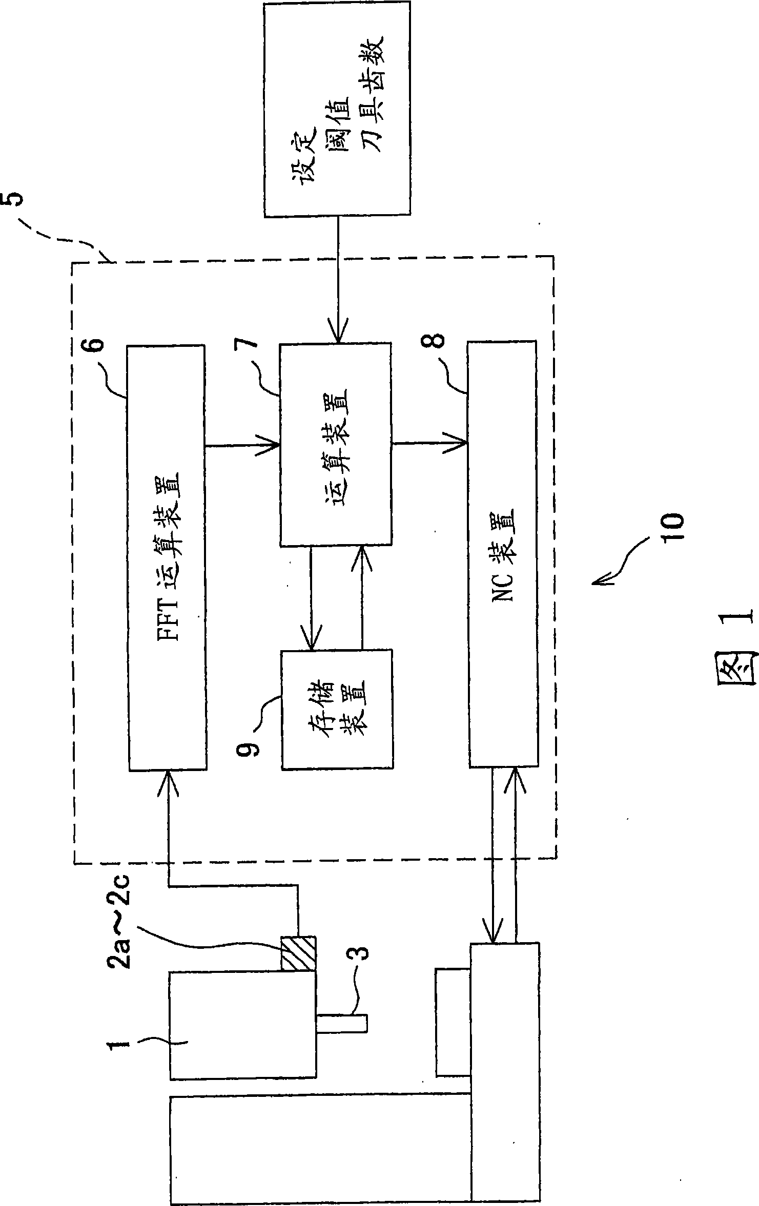
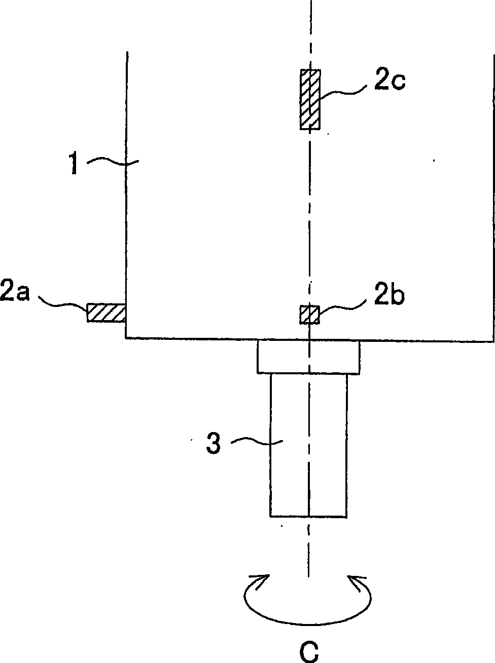
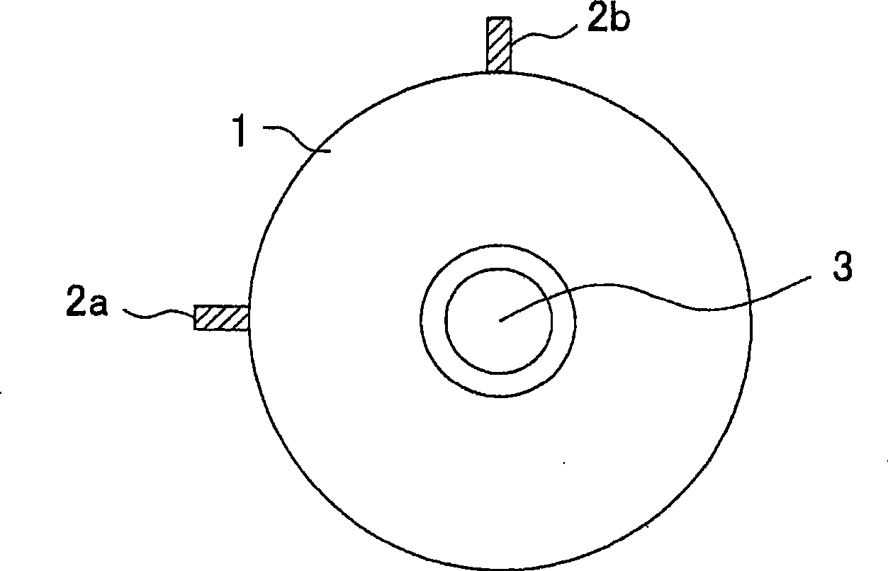
[0034] FIG. 1 is a schematic diagram showing a frame configuration of a vibration suppressing device 10 . figure 2 It is a schematic diagram showing the rotating shaft housing 1 to be subjected to vibration suppression from the side, image 3 It is a schematic diagram showing the rotating shaft housing 1 from the axial direction.

[0035] The vibration suppressing device 10 is used to suppress the "flutter" generated on the rotating shaft 3 that is provided in the rotating shaft housing 1 and can rotate along the C-axis system, by detecting the vibration acceleration of the time re...


PUM


Abstract

The present invention provides a vibration suppressing device which can calculate the optimal rotation speed that can effectively suppress oscillation, wherein the device comprises the following components: vibration sensors (2a-2c) which detect the vibration acceleration of time region of a rotating shaft (3) in the rotating process; an FFT calculating device (6) which calculates an oscillation number and the vibration acceleration of frequency region under the oscillation number according to the detected vibration acceleration of time region; a storing device (9) which stores the vibration acceleration and oscillation number of frequency region as processing information; a calculating device (7) which stores a maximum acceleration and oscillation number in the storing device (9) as new processing information when the calculated maximum acceleration of the frequency region exceeds a preset threshold, and furthermore calculates the optimal rotation speed which can suppress the oscillation according to the new processing information and the last processing information stored in the storing device (9); and a NC device (8) which rotates the rotating shaft at the optimal rotation speed.

Description

technical field [0001] The present invention relates to a method of suppressing vibration generated during machining in a machine tool that performs machining while rotating a tool or a workpiece, and a vibration suppressing device capable of performing the method. Background technique [0002] As a conventional vibration suppression method for machine tools, a method described in Patent Document 1 below is known. In this vibration suppression method, in order to suppress regenerative chatter as a self-excited vibration that causes deterioration of the machining accuracy of the machined surface, the natural vibration number of the system that generates chatter, such as the tool and the workpiece, is obtained and set to 60 The value obtained by dividing by the number of teeth of the tool and a predetermined integer is taken as the rotation speed (steady rotation speed). The natural vibration number is obtained by pulse-exciting the tool and the workpiece. [0003] Furthermo...

Claims


Application Information

Patent Timeline
IPC IPC(8): B23Q11/00
Inventor 稻垣浩
Owner OKUMA CORP
Why Eureka
Eureka Blog
Learn More