Solar energy film battery laser engraving device and method

A technology of solar thin film and laser etching, applied in laser welding equipment, welding equipment, metal processing equipment, etc., can solve the difficulty of installing the feeding and discharging conveying system, the difficulty of improving the air quality of the station, and the Y-axis motion system Long length and other problems, achieve the effect of automatic feeding and discharging, short length, and reduce labor intensity

Active Publication Date: 2009-04-29
HANS LASER TECH IND GRP CO LTD
View PDF0 Cites 8 Cited by
  • Summary
  • Abstract
  • Description
  • Claims
  • Application Information

AI Technical Summary

Problems solved by technology

[0006] 1. Low production efficiency: Even if dual laser etching heads are used, both sides of the workpiece can only be etched in the Y-axis direction at the same time. In the X-axis direction, it is impossible to etch both sides of the workpiece at the same time, and the production efficiency is low
[0007] 2. The feed distance in the Y-axis direction is large, and the length of the Y-axis motion system is too long
[0008] 3. The workpiece fixture moves along the Y-axis direction with the Y-axis motion system during the working process, which brings difficulties to the installation of the feeding conveying system and the discharging conveying system, which is not convenient for automatic production
[0009] 4. The X-axis frame is installed across the top of the Y-axis frame through the column installed on the Y-axis frame. It is difficult to install a dust exhaust system. The dust generated by etching cannot be removed, and it is difficult to improve the air quality of the workstation.

Method used


Image

  • Solar energy film battery laser engraving device and method
  • Solar energy film battery laser engraving device and method
  • Solar energy film battery laser engraving device and method

Examples


Embodiment Construction

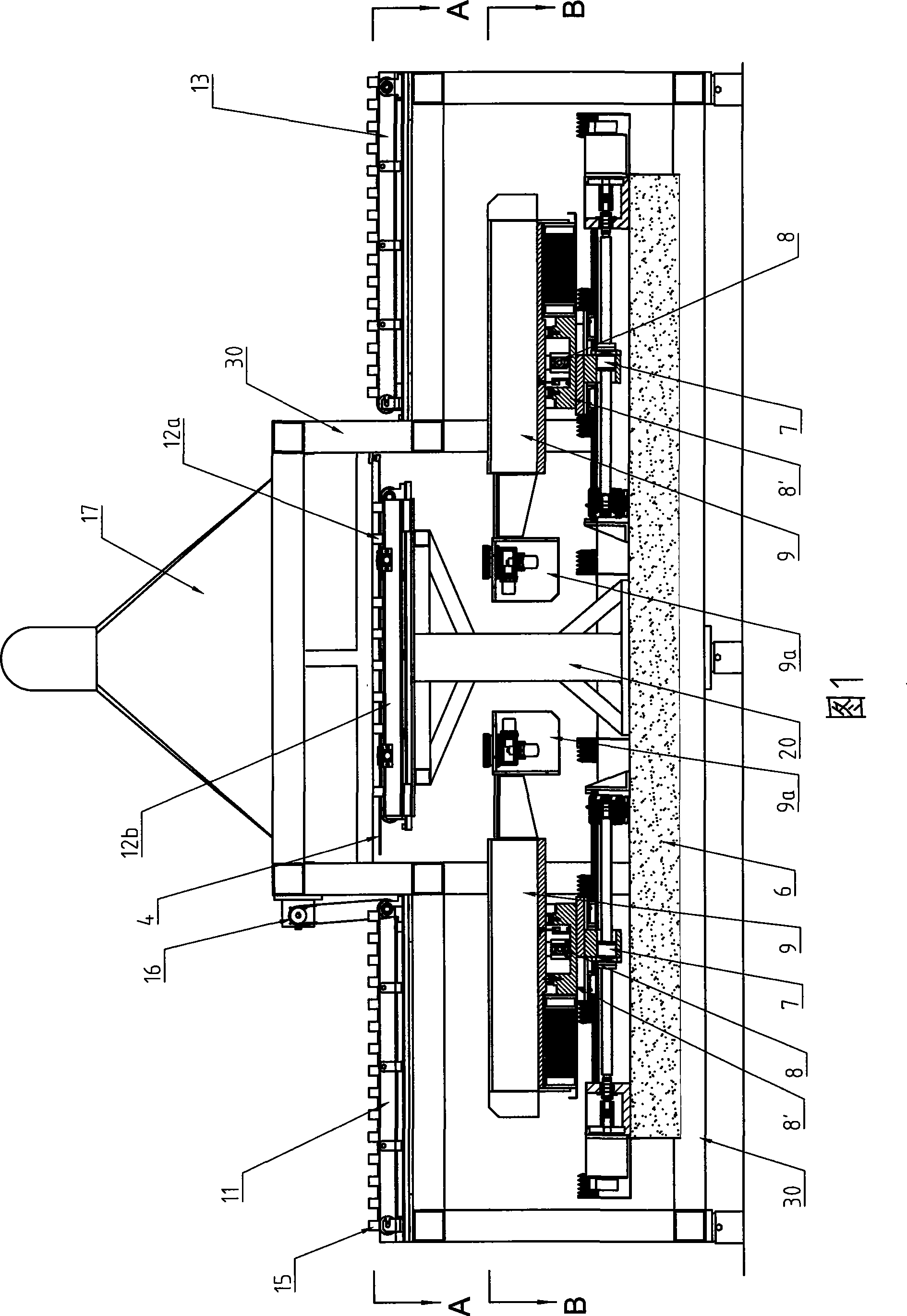
[0035] The laser etching equipment of the present invention is used to etch and remove the film on the edge of the amorphous silicon thin film solar cell, and the shaded part shown in FIG. 4 is the part to be etched on the edge of the amorphous silicon thin film solar cell.

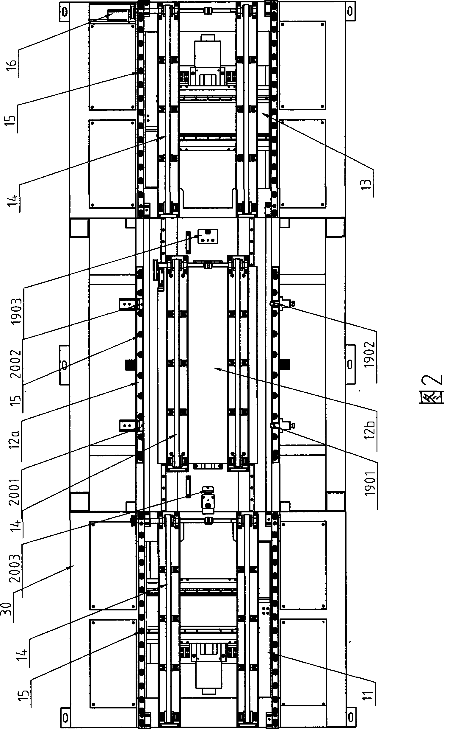
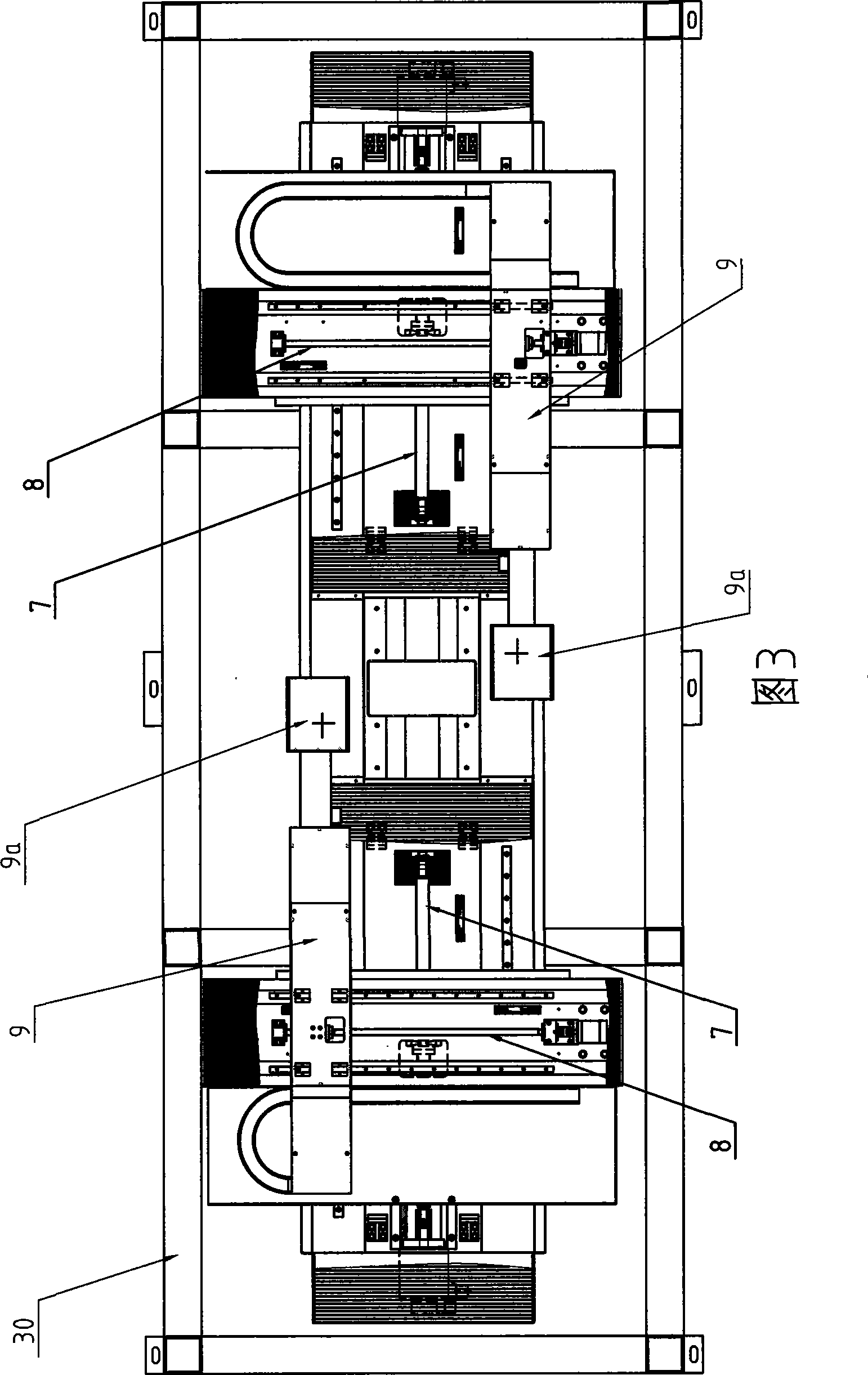
[0036] As shown in FIGS. 1 to 8 , the embodiment of the laser etching equipment for solar thin film cells of the present invention includes a frame 30 , a marble Y-axis base 6 , and the marble Y-axis base 6 is installed on the frame 30 . Two sets of the same etching system are installed on the Y-axis base 6 , and the two sets of etching systems are arranged opposite to each other on the Y-axis base 6 . Each etching system has an X-axis motion system 8, an X-axis base 8', a Y-axis motion system 7 and a laser system 9. The X-axis motion system 8 is installed on the X-axis base 8', the X-axis base 8' is installed on the Y-axis motion system 7, and the Y-axis motion system 7 is installed on the Y-axis base 6 ...


PUM


Abstract

The invention discloses laser etching equipment of a solar thin film cell and an etching method. The equipment comprises two sets of etching systems which are distributed on a Y shaft base oppositely; each set of etching system comprises an X shaft motion system, a Y shaft motion system and a laser system; the X shaft motion system and the Y shaft motion system form a cross sliding table structure; a workpiece clamp is positioned at the upper part of the central part of the Y shaft base; a periphery clamping device of the workpiece clamp is arranged on a rack; a center support device of the workpiece clamp is arranged on a pillar which is positioned at the central part of the Y shaft base; the laser system is arranged on the X shaft motion system; and an etching head of the laser system extends to the lower part of the workpiece clamp. The invention has short feeding distance along the Y shaft direction; and the two sets of etching system work simultaneously, respectively do etching motion along a U-shaped path and etch coating layers of belt areas which are 10mm from the periphery of the workpiece in a combining mode, thus simplifying the production technique and improving the production efficiency, yield and production quality.

Description

[technical field] [0001] The invention relates to the technical field of laser cutting, in particular to a laser etching device and an etching method for solar thin film cells. [Background technique] [0002] With the rapid development of modern industry, the rapid upgrading of technology and the demand for energy, the energy structure is undergoing fundamental changes. The traditional energy: coal, oil, and natural gas will reach their peak in 2020-2040 , and will gradually dry up after 2050, alternative energy, renewable energy (mainly solar energy) has developed rapidly since 2000, and its usage will reach its peak by 2050. Traditional solar cells use monocrystalline silicon or polycrystalline silicon thin slices, which use a lot of silicon materials, resulting in serious waste, and the silicon element purification process is complicated and costly. Amorphous silicon thin-film solar cells use a small amount of silicon, so there is no raw material bottleneck, low cost, an...

Claims


Application Information

Patent Timeline
IPC IPC(8): B23K26/38B23K26/40B23K26/08H01L31/18B23K26/362B23K26/402
CPCY02P70/50
Inventor 高云峰陈明金吴志宏倪鹏玉谢建李世印郑国云
Owner HANS LASER TECH IND GRP CO LTD
Why Eureka
Try Eureka