
Turbocharging system for adjusting exhausting pipe volume by rotating baffle

A turbocharging system and exhaust pipe technology, applied in the field of internal combustion engine turbocharging systems and turbocharging systems, can solve problems such as low turbine efficiency, small exhaust pipe volume, and not the best operating effect, and achieve reasonable design , the effect of excellent performance

Inactive Publication Date: 2009-04-22
SHANGHAI JIAO TONG UNIV
View PDF1 Cites 65 Cited by
  • Summary
  • Abstract
  • Description
  • Claims
  • Application Information

AI Technical Summary

Problems solved by technology

The volume of the exhaust pipe of the pulse supercharging system is small, the entropy increase of the exhaust gas from the exhaust valve to the turbine inlet is small, the exhaust energy utilization rate is high, and the load change can be reflected in time, and the response speed is fast; However, because the turbine is pulsating intake air, resulting in low turbine efficiency, the pulse supercharging system is beneficial for low load and transient conditions
It can be seen that if an engine is equipped with constant pressure supercharging method and pulse supercharging method at the same time, the constant pressure supercharging system is used at high load, and the pulse supercharging system is used at low load and transient working conditions, which is more ideal. Yes, but the volume of the exhaust pipe of the existing engine supercharging system cannot be adjusted
Modular pulse conversion supercharging system combines the advantages of constant pressure supercharging and pulse supercharging, but its operation effect is not the best at the lowest load and the highest load

Method used


Image

  • Turbocharging system for adjusting exhausting pipe volume by rotating baffle
  • Turbocharging system for adjusting exhausting pipe volume by rotating baffle

Examples


Embodiment Construction

[0010] The specific implementation of the present invention will be further described below in conjunction with the accompanying drawings.

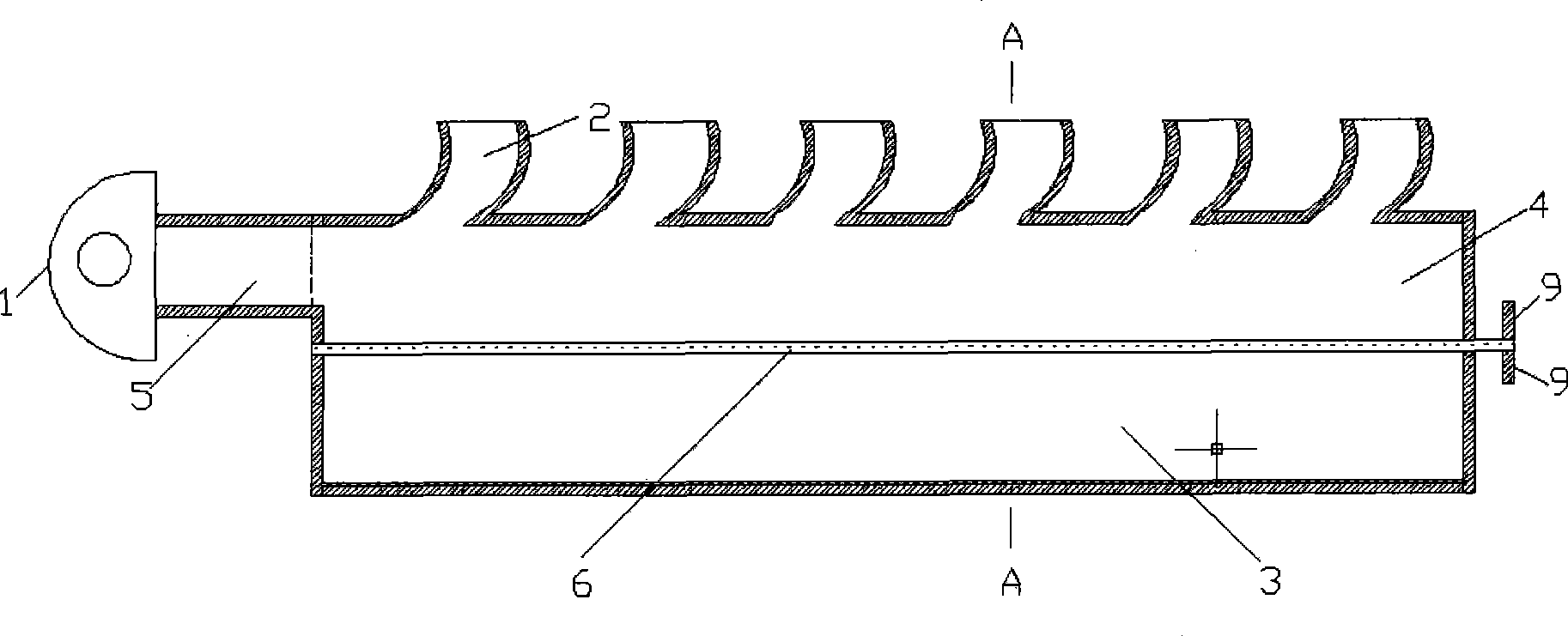
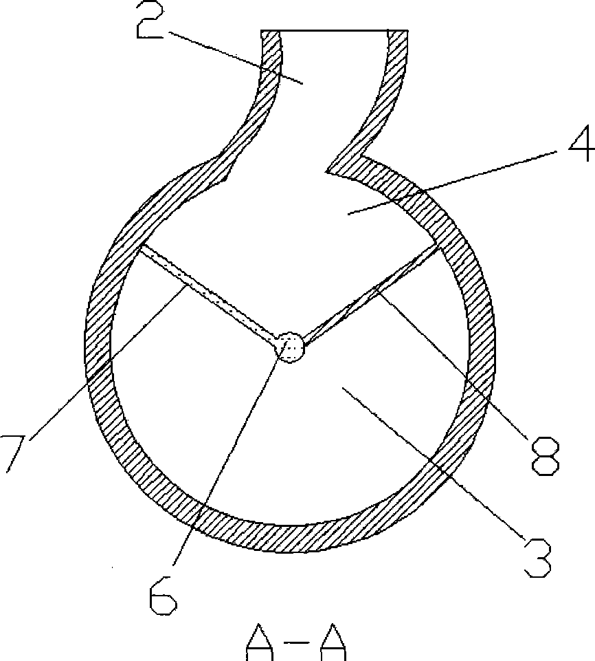
[0011] Such as figure 1 , figure 2 As shown, the present invention includes an exhaust branch pipe 2, an exhaust pipe 4, a turbine 1, a connecting pipe 5, a volume adjustment pipe 3, a partition shaft 6, a first partition 7, a second partition 8 and a partition rotation handle 9 , the inlet of the exhaust branch pipe 2 is connected to the exhaust port of the cylinder head, the outlet of the exhaust branch pipe 2 is connected to the exhaust pipe 4, the turbine 1 is a single inlet turbine, and the volume regulating pipe 3 is a large round pipe; the partition shaft 6 One end is placed in the groove at the center of the front end surface of the volume adjustment tube 3, the other end passes through the center of the rear end surface of the volume adjustment tube 3 and extends out of the volume adjustment tube 3, and the partition rotating h...


PUM


Abstract

The invention relates to a turbocharging system through utilizing the rotation of a clapboard to adjust the cubage of an exhaust pipe and belongs to the technical field of internal combustion engine. The turbocharging system comprises an exhaust branch pipe, the exhaust pipe, a connecting pipe, a cubage adjusting pipe, a turbine, a clapboard shaft and clapboards; the clapboard shaft is arranged between the center of the front end face of the cubage adjusting pipe and the center of the rear end face of the cubage adjusting pipe; a first clapboard and a second clapboard are arranged between the clapboard shaft and the inner sidewall of the cubage adjusting pipe; and the cubage of the exhaust pipe is adjusted through rotating the clapboards. When the working condition is lowered, the clapboards rotate so as to lessen the cubage of the exhaust pipe; and when the working condition is heightened, the clapboards rotate so as to enlarge the cubage of the exhaust pipe. The turbocharging system has the advantages that the turbocharging system has reasonable design, meets the operation requirement of variable working conditions of the engine, is not limited by the number of cylinders and is suitable for the turbocharging system the turbine of which is provided with a single inlet and laterally arranged.

Description

technical field [0001] The invention relates to a turbocharging system of an internal combustion engine, in particular to a turbocharging system with a single inlet of the turbine and the side of the turbine, which uses the rotation of a partition to adjust the volume of an exhaust pipe, and belongs to the technical field of the internal combustion engine. Background technique [0002] With the development of society and the improvement of environmental protection requirements, engine boosting technology is now more and more widely used. Most of the medium and high-power engines use turbocharging technology to increase power and reduce fuel consumption. The two basic supercharging systems for turbocharged engines are constant pressure supercharging system and pulse supercharging system. The structural feature of the constant pressure booster system is that the volume of the exhaust pipe is large, the exhaust pipe plays a role in stabilizing the pressure, the fluctuation of t...

Claims


Application Information

Patent Timeline
Patent Type & Authority Applications(China)
IPC IPC(8): F02B37/12F02C6/12
CPCY02T10/144Y02T10/12
Inventor 邓康耀王绍明崔毅田中旭石磊
Owner SHANGHAI JIAO TONG UNIV
Learn More