Substrate provided with an electroconductive element having an antenna function

A technology for conducting elements and substrates, applied in electrical elements, antenna parts, antennas, etc., can solve problems such as complex implementation, and achieve the effect of reducing the area, increasing the manufacturing cost, and improving the durability.

Inactive Publication Date: 2009-04-15
SAINT-GOBAIN GLASS FRANCE
View PDF3 Cites 5 Cited by
  • Summary
  • Abstract
  • Description
  • Claims
  • Application Information

AI Technical Summary

Problems solved by technology

However, the implementation of this fabrication process remains complex

Method used


Image

  • Substrate provided with an electroconductive element having an antenna function
  • Substrate provided with an electroconductive element having an antenna function
  • Substrate provided with an electroconductive element having an antenna function

Examples


Embodiment Construction

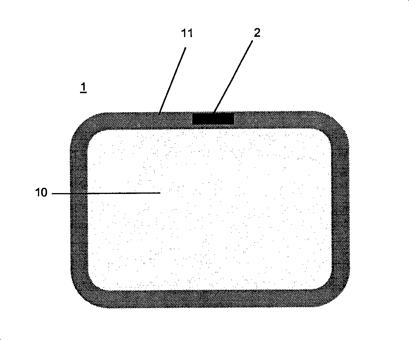
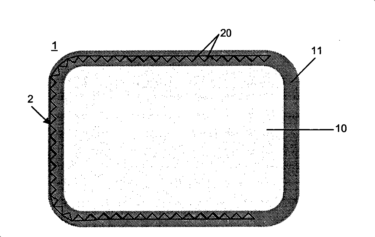
[0057] figure 1 A glazing 1 according to the invention is shown comprising a glass substrate 10 which has been heat-treated and which comprises an antenna structure 2 .

[0058] The substrate can also be made of polycarbonate or polymethyl methacrylate, which are rigid plastics especially suitable for carrying conductive inks or pastes by screen printing.

[0059] For example, glazing can be used in motor vehicles as a windshield, rear window, side window, roof or rear view window. The shapes shown here are schematic - any shape of the glazing or enamel wall is conceivable which is suitable for the arrangement for the glazing or wall.

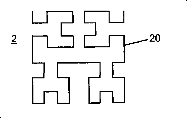
[0060] Antenna structure 2 is a fractal geometry ( figure 2 ) antenna. Said antenna comprises conductive elements 20 in segmented form, arranged in series and in parallel, possibly in different and similar dimensional ratios, in a manner that forms a pattern that repeats itself many times.

[0061] figure 2 The pattern shown is an exampl...


PUM


Abstract

Rigid substrate (10) comprising at least one electroconductive element (20) which provides an antenna function for transmitting and / or receiving electromagnetic signals, the electroconductive element having a fractal pattern, characterized in that the electroconductive element (20) consists of an electrically conducting ink or enamel that is printed directly on the substrate.

Description

technical field [0001] The invention relates to a substrate comprising at least one conductive element providing an antenna function for transmitting and / or receiving electromagnetic signals. Background technique [0002] Glazing is one of the known substrates comprising conductive elements and is widely used in the automotive field. Conductive elements are usually used as heating tracks, especially on the rear window, but they may also be provided on the window glass to provide an alarm and / or antenna function there. [0003] In practice, the conductive elements are made of metal lines formed by conventional screen printing of a conductive paste, forming a predetermined pattern and firing the paste. [0004] The pattern provides the element with a precise width and a precise thickness depending on the final function of the element, eg with respect to the required impedance of the antenna. [0005] Due to the beneficial functions provided by these conductive elements (heat...

Claims


Application Information

Patent Timeline
IPC IPC(8): H01Q1/32H01Q1/12H01Q1/36H01Q1/38
CPCH01Q1/38H01Q1/36H01Q1/1278H01Q1/1271H01Q1/3266H01Q1/364
Inventor S·科利内J·热姆克鲁萨多
Owner SAINT-GOBAIN GLASS FRANCE
Why Eureka
Try Eureka