
Two-stage turbo-charger engine system

A turbocharging and engine technology, applied in the direction of machines/engines, mechanical equipment, engine components, etc., can solve problems such as low performance and loss of heat energy, and achieve high performance, improved performance, and low pressure drop

Active Publication Date: 2009-04-15
GM GLOBAL TECH OPERATIONS LLC
View PDF1 Cites 8 Cited by
  • Summary
  • Abstract
  • Description
  • Claims
  • Application Information

AI Technical Summary

Problems solved by technology

Cars equipped with this engine have unnecessarily low performance and lose heat energy when regenerating the Diesel Particulate Filter (DPF)

Method used


Image

  • Two-stage turbo-charger engine system
  • Two-stage turbo-charger engine system
  • Two-stage turbo-charger engine system

Examples


Embodiment Construction

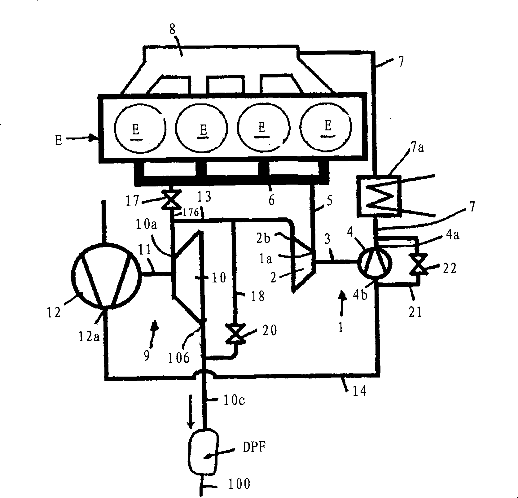
[0023] figure 1 The structure of an embodiment of the turbocharged engine system according to the invention is shown.

[0024] The turbocharged engine system has an engine E with 4 cylinders Z, a high-pressure turbocharger 1 , a low-pressure turbocharger 9 and a diesel particulate filter DPF. For clarity, other components of engine E are in figure 1 not drawn in.

[0025] The high-pressure turbocharger 1 comprises a high-pressure turbine 2 and a high-pressure compressor 4 driven by the high-pressure turbine 2 via a shaft 3 . The high-pressure turbine inlet 1 a is communicatively connected to an exhaust manifold 6 of the engine E through a high-pressure exhaust pipe 5 . The high-pressure exhaust pipe 5 is also called a high-pressure turbine connection pipe. The high-pressure compressor outlet 4a is communicatively connected to the intake manifold 8 of the engine E through the high-pressure intake pipe 7 . An intercooler 7 a is provided in the high-pressure intake pipe 7 . ...


PUM


Abstract

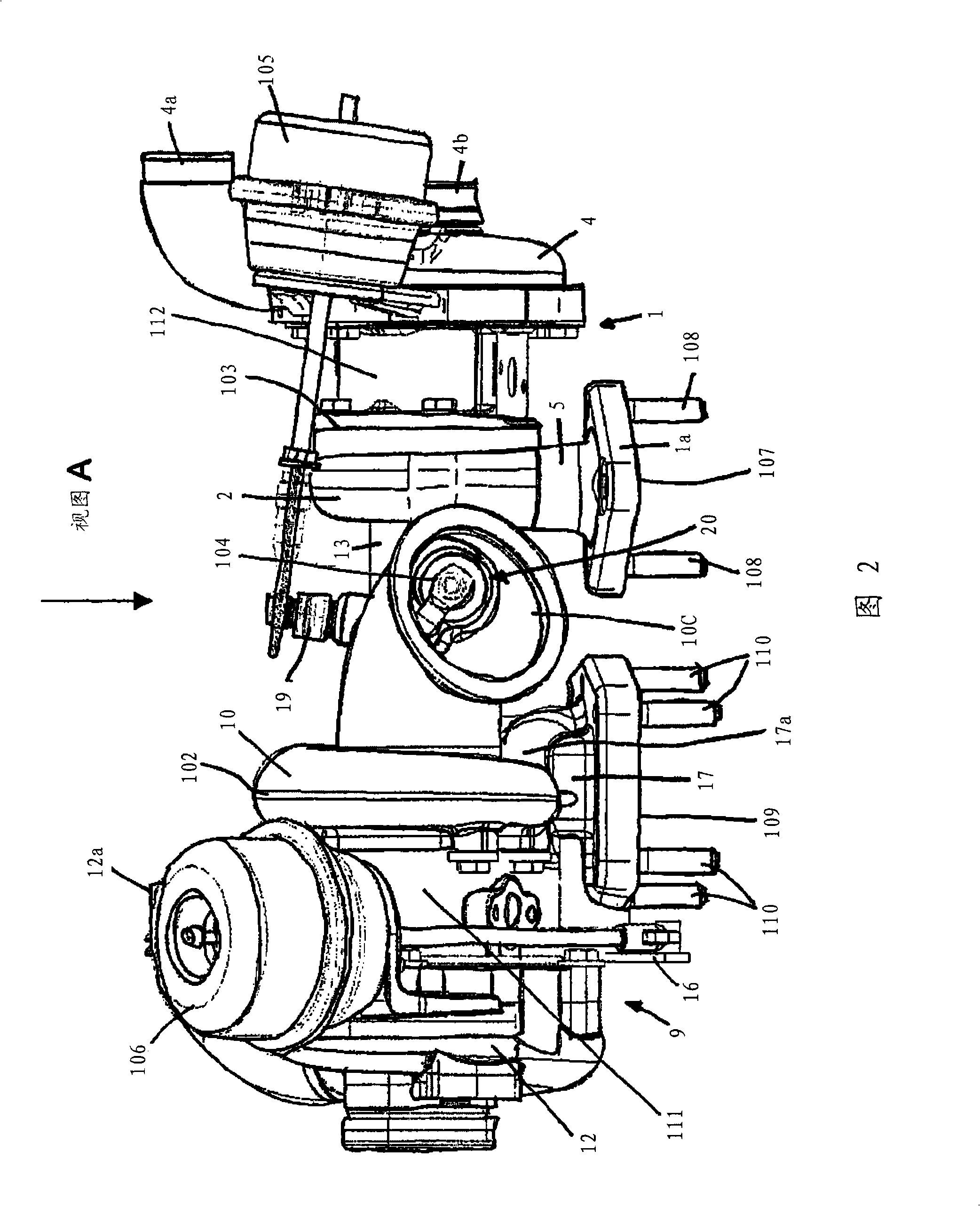
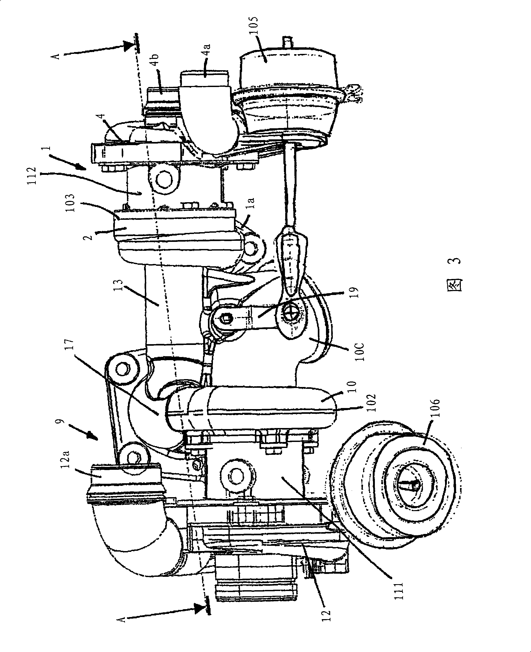
A turbine housing (101) for a high-pressure turbo-charger (1) of a turbo-charger engine system for an internal combustion engine (E) comprises a low-pressure charger opening (102) for taking up a low-pressure turbo-charger (9) and a high-pressure charger opening (103) for taking up a high-pressure turbo-charger (1). A high-pressure exhaust opening (107) is attached to a corresponding flange at an exhaust manifold (6) of the engine (E) and there is a short-cut exhaust opening (109) with a high-pressure turbine by-pass valve area (17) attached to a corresponding flange at the exhaust manifold (6). An external connection opening (10c) is attached to a muffler, a waste gate valve area (20) being provided in the close vicinity of the external connection opening (10c).

Description

technical field [0001] The present invention relates to a two-stage turbocharged engine system for an internal combustion engine. Background technique [0002] Such a two-stage turbocharged engine system is disclosed in US 4930315. This turbocharged system also suffers from the difficulty of installing a diesel particulate filter on it. Typically, one places an oxidation catalyst near the engine and a diesel particulate filter under the chassis. Cars equipped with such engines have unnecessarily low performance and lose heat energy when regenerating the Diesel Particulate Filter (DPF). Contents of the invention [0003] The technical problem to be solved by the present invention is to provide a motor vehicle with a clean and powerful engine within the framework of existing vehicle platforms. [0004] This technical problem is solved by the subject-matter of the independent claims. The respective dependent claims give various advantageous developments. [0005] The pre...

Claims


Application Information

Patent Timeline
IPC IPC(8): F02B37/013
CPCF02B37/183F02B37/013F02B37/002F02B37/18Y02T10/144F02B37/004F02B37/16F01N3/02Y02T10/20Y02T10/12
Inventor 帕尔·阿克塞尔森汉斯·德兰盖尔比约恩·林德
Owner GM GLOBAL TECH OPERATIONS LLC
Learn More