
Circuit disconnector

A technology of circuit disconnection and disconnector, applied in circuits, circuit breaker parts, electrical components, etc., to prevent misconnection

Active Publication Date: 2009-04-15
KAWAMURA ELECTRIC INC
View PDF4 Cites 3 Cited by
  • Summary
  • Abstract
  • Description
  • Claims
  • Application Information

AI Technical Summary

Problems solved by technology

For example, Patent Document 2 describes that near the terminal opening of the load-side terminal, inside the disconnector housing, an up-and-down long display member is rotatably supported back and forth, and whether the wire is connected to the speed is displayed by the rotational position of the display member. The technique that the knot terminal fitting is connected surely

Method used


Image

  • Circuit disconnector
  • Circuit disconnector
  • Circuit disconnector

Examples


Embodiment 1

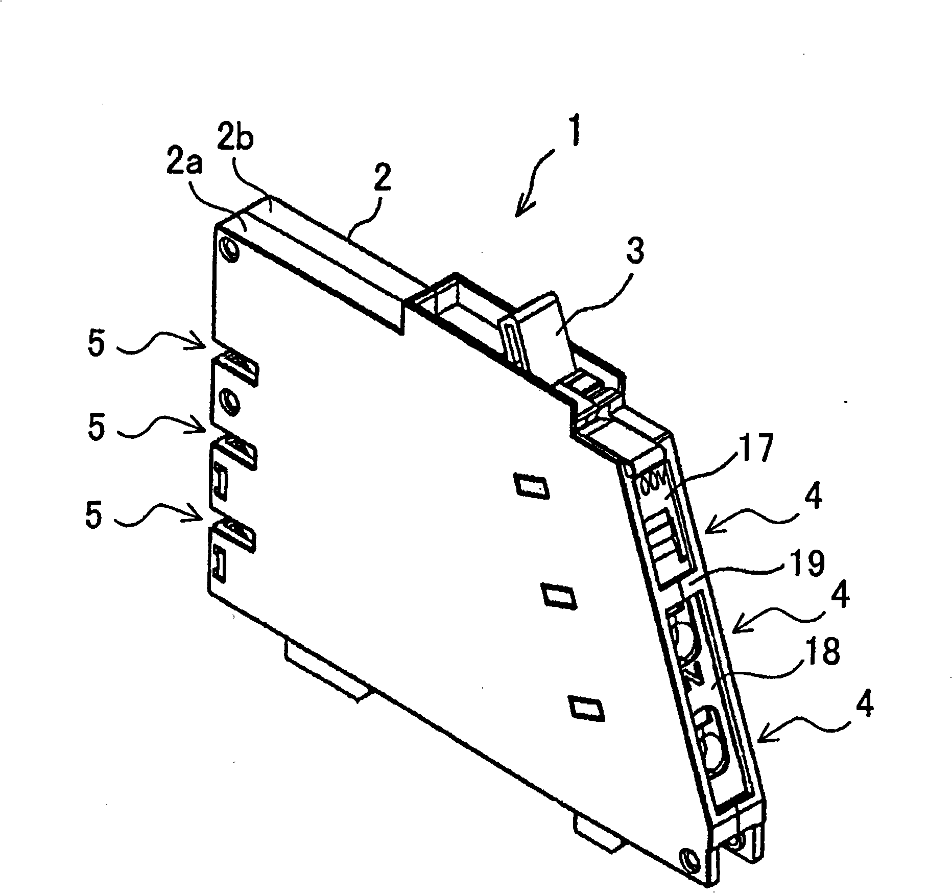
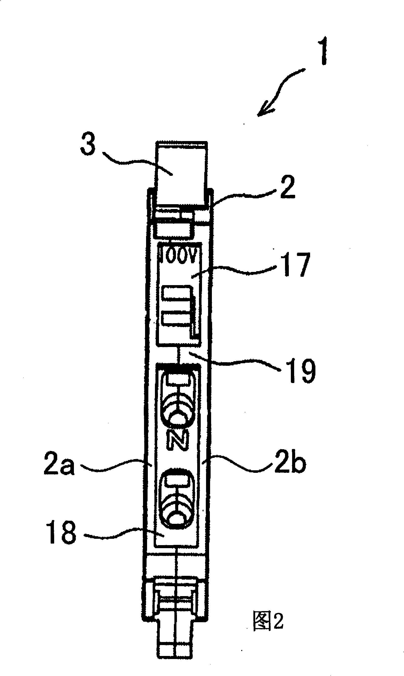
[0073] Such as figure 1 , As shown in FIG. 2 , the circuit breaker 1 of the first embodiment has a synthetic resin breaker case 2 . The disconnector housing 2 is formed by combining a pair of left and right divided bodies 2a and 2b, and is formed in a square thin box shape. On the upper surface of the disconnector case 2, an operation lever 3 for opening and closing the circuit is provided so as to be rotatable in the forward and rearward directions. Three load-side terminals 4 and power-side terminals 5 are arranged in a row in the vertical direction on the front and rear surfaces of the disconnector case 2, respectively. An overcurrent detection mechanism and a disconnection mechanism (not shown) are provided inside the disconnector case 2, and when an overcurrent is detected, the circuit between the power supply side terminal 5 and the load side terminal 4 is disconnected.

[0074] Such as image 3 As shown in Figure 5, the power supply side terminal 5 is a plug-in termi...

Embodiment 2

[0093] Second, based on Figure 13 to Figure 16 Embodiment 2 of the circuit breaker according to the present invention will be described. The circuit breaker 51 of the second embodiment differs from the circuit breaker 1 of the first embodiment in the configuration of a member that covers the terminal holes 7 of the load-side terminals 4 . The other configurations are the same as those in Embodiment 1, and the same symbols are assigned to the drawings, and description thereof will be omitted.

[0094] Such as Figure 13 As shown, a cover member 18 for opening and closing the insertion opening 12 of the load-side terminal 4 and a sealing cover 52 for selectively covering the terminal opening 7 are installed between the front ends of the split bodies 2a and 2b of the disconnector housing 2. . The sealing cover 52 has an insertion portion 53 removably inserted into a selected one of the terminal openings 7 and an engaging portion 54 engaging with the front surface of the disco...


PUM


Abstract

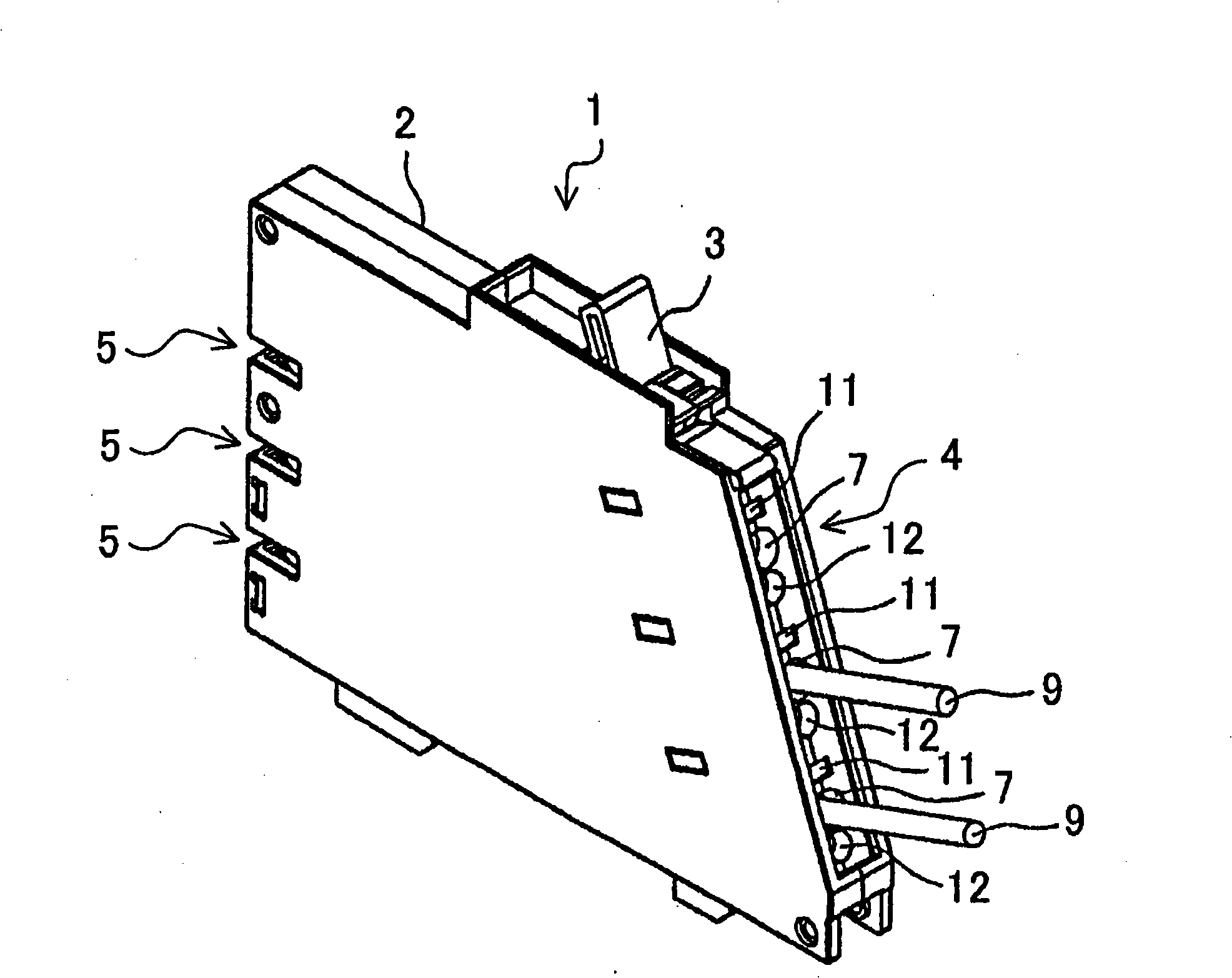
The invention relates to a circuit decoupler which does not thicken a decoupler casing and can improve the function of a load side terminal. In the circuit decoupler (1) used in a single phase three-wire type circuit, an operating lever (3) which switches on and off the circuit is arranged on a thin box shaped decoupler casing (2). Three load side terminals (4) and power supply side terminals (5) are respectively arranged along the up-down direction on the front and the back of the decoupler casing (2). A terminal opening (7) which is used for connecting an electrical wire (9) with a quick terminal joint of the load side terminals (4) is arranged on the front of the decoupler casing (2). A confirming window (11) which is used for confirming the connection state of the electrical wire (9) is formed at the upper side of the terminal opening (7). A plug-in opening (12) which is sued for the electric connection of a measuring terminal of a measuring apparatus and the quick terminal joint is arranged at the lower side of the terminal opening (7). A display mechanism is arranged in the decoupler casing (2) at the back of the confirming window (11).

Description

technical field [0001] The present invention relates to a thin circuit breaker installed in a switchboard or the like, and particularly relates to a structure around a load-side terminal. Background technique [0002] Conventionally, a circuit breaker has been proposed in which the width of the disconnector case is reduced so that it can be installed compactly in a switchboard. For example, Patent Document 1 describes that an operating lever for opening and closing the circuit is provided on the upper surface of the disconnector case, and a plurality of load-side terminals are arranged vertically on the front and back of the disconnector case. A circuit breaker for single-phase three-wire circuits with terminals on the power supply side. [0003] Also, conventionally known is a circuit breaker in which quick-connect terminals for easy connection of electric wires are used as load-side terminals. For example, Patent Document 2 describes that near the terminal opening of the...

Claims


Application Information

Patent Timeline
Patent Type & Authority Applications(China)
IPC IPC(8): H01H71/08H01H73/20H01H71/02H01H73/06H01R4/48
Inventor 加藤裕明
Owner KAWAMURA ELECTRIC INC
Learn More