
Drum type washing machine

A drum-type washing machine, a washing machine technology, applied to other washing machines, control devices of washing machines, washing devices, etc., can solve the problems such as the inability to operate the electric motor and the temperature rise of the first electric motor.

Active Publication Date: 2009-04-15
PANASONIC CORP
View PDF3 Cites 4 Cited by
  • Summary
  • Abstract
  • Description
  • Claims
  • Application Information

AI Technical Summary

Problems solved by technology

[0013] However, in the above-mentioned conventional drum type washing machine, when agitation is started during the washing process, a high torque may be applied to the first motor, and the first motor may be demagnetized, so that the rotation of the drum cannot be started.
In addition, when a load is continuously applied to the first motor, the temperature of the first motor rises, making it impossible to drive the motor.

Method used


Image

  • Drum type washing machine
  • Drum type washing machine
  • Drum type washing machine

Examples


Embodiment approach 1

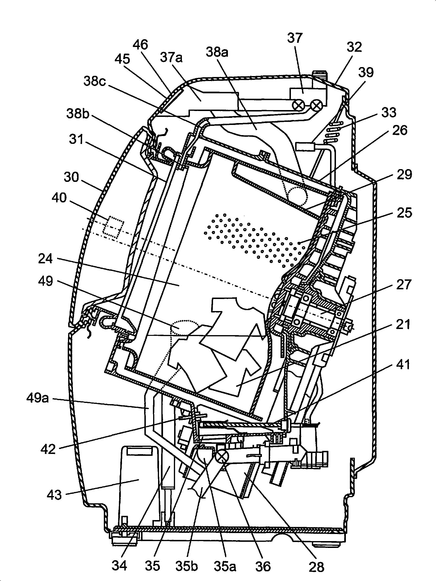
[0037] figure 1 It is a longitudinal sectional view of the front-loading-type washing machine in Embodiment 1 of the present invention. Such as figure 1 As shown, the rotary drum 24 is formed in a bottomed cylindrical shape, and a plurality of water passage holes 25 are provided on the entire outer peripheral surface thereof, and the rotary drum 24 is rotatably arranged in a water tank 26 . A rotating shaft (rotation center axis) 27 is provided substantially obliquely at the center of rotation of the rotating drum 24, and the rotating drum 24 is arranged so that the axial direction of the rotating drum 24 is inclined downward from the front side toward the rear side. A motor 28 attached to the back surface of the water tank 26 is connected to the rotating shaft 27, and the motor 28 drives the rotary drum 24 to rotate in the forward rotation direction and the reverse rotation direction. Several protruding plates 29 are arranged on the inner wall of the rotary drum 24, which...

Embodiment approach 2

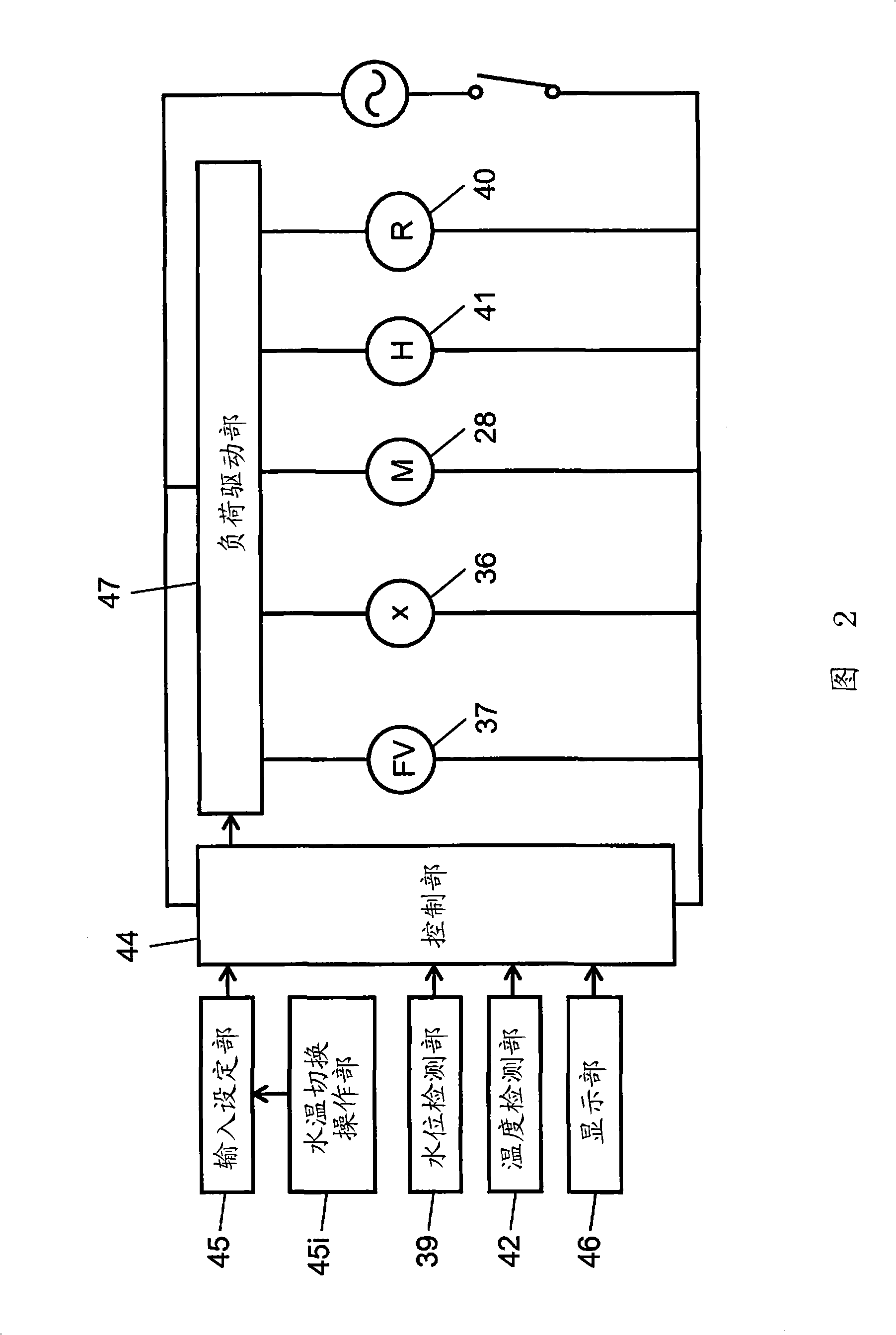
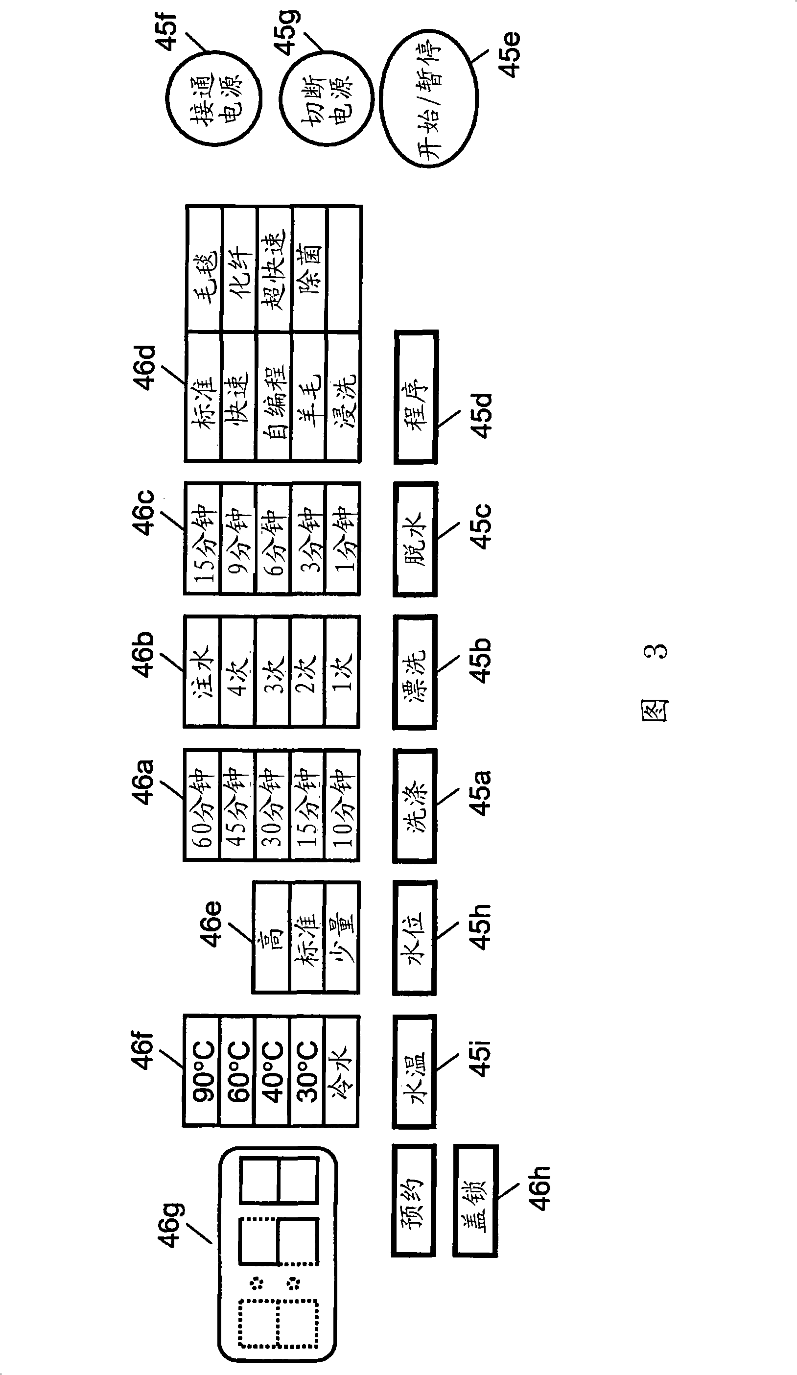
[0077] Figure 8A , Figure 8B It is a flow chart of the operation of main parts of the front-loading-type washing machine according to Embodiment 2 of the present invention. Since the longitudinal sectional view, module control circuit diagram, input setting unit, and display unit of the drum-type washing machine according to Embodiment 2 of the present invention are the same as those of the drum-type washing machine according to Embodiment 1 of the present invention, the same reference numerals are assigned to the same structural elements, Its description is omitted.

[0078] Such as Figure 8A , Figure 8B As shown, in the second agitation process of the front-loading-type washing machine according to Embodiment 2 of the present invention, when the rotation of rotary drum 24 is temporarily stopped, the process shifts to the first agitation process. More specifically, in the second stirring process, stirring 2 is performed in step 112 . Then, when the stirring time S ha...


PUM


Abstract

The present invention provides a drum type washing machine, wherein, the drum type washing machine includes a rotary drum, a sink, a washing machine main body, a cover, a motor, a water-supply section, a water drainage section, a water level detection section and a control device. The washing and rinsing process includes a first mixing process and a second mixing process; in the first mixing process, the rotary drum repeatedly turns, stops, reverses, stops; in the second mixing process, the rotary drum performs rapid arc rotation, and a centrifugal force produced by the rapid arc rotation of the rotary drum is used to raise up the washings, and then the motor rotation is quickly braked, so that the washings, positive and negative alternately, repeatedly performs a fall action to a side opposite to the right and left direction of the raising a the lower part of the rotary drum; it is transferred to the first mixing process when at least one time that the mixing is unable to start up in the second mixing process.

Description

technical field [0001] The present invention relates to a drum type washing machine which performs washing, rinsing and dehydration in a rotating drum having a rotating central axis along a horizontal direction or an inclined direction. Background technique [0002] For example, Japanese Patent Application Laid-Open No. 10-263285 (Patent Document 1) discloses a conventional drum-type washing machine. Figure 9 It is a vertical cross-sectional view of a conventional front-loading washing machine disclosed in Patent Document 1. FIG. Next, the configuration of a conventional drum-type washing machine will be described. [0003] Such as Figure 9 As shown, the rotating drum 201 is provided with many water passage holes 202 on the entire surface of its outer periphery, and the rotating drum 201 is freely rotatably arranged in the outer tank 203 . One end of a rotating shaft 204 is fixed substantially horizontally to the center of rotation of the rotating drum 201 , and a driven ...

Claims


Application Information

Patent Timeline
IPC IPC(8): D06F37/02D06F33/02D06F37/00
Inventor 皆吉裕子萩原久齐藤弘幸
Owner PANASONIC CORP
Learn More