Field magnet frame for removing iron dust in plastic

A technology of using magnets and iron filings, applied in the field of magnet racks for removing iron filings from plastics, can solve the problems of insufficient adsorption of iron filings powder, loss of magnetism of magnet bars, and difficulty in breaking apart and cleaning, so as to reduce the influence of the flow direction of objects and prolong The effect of long service life and simple structure

Inactive Publication Date: 2009-04-15
SHANGHAI KINGFA SCI & TECH +1
View PDF0 Cites 0 Cited by
  • Summary
  • Abstract
  • Description
  • Claims
  • Application Information

AI Technical Summary

Problems solved by technology

The disadvantages of this device are 1. Due to the disordered arrangement of the magnet rods when they are cross-adsorbed, the adsorption of iron filings powder is insufficient; 2. Due to the disordered arrangement of the magnet rods when they are cross-adsorbed, it is easy to cause the The feeding is not smooth; 3. The magnetic bar has strong magnetism, and it is not easy to break apart and clean after being adsorbed together; 4. There is a certain distance between the place where the magnetic bar is placed and the opening of the feeding tank, and it is often thrown directly to the feeding port during manual operation. Since there is no protective device for the magnetic bar, frequent beatings will cause the magnet bar to lose its magnetism, shorten the service life, reduce production efficiency and increase the cost

Method used


Image

  • Field magnet frame for removing iron dust in plastic
  • Field magnet frame for removing iron dust in plastic
  • Field magnet frame for removing iron dust in plastic

Examples


Embodiment Construction

[0019] The present invention will be further described below in conjunction with accompanying drawing and specific embodiment:

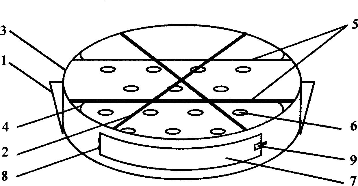
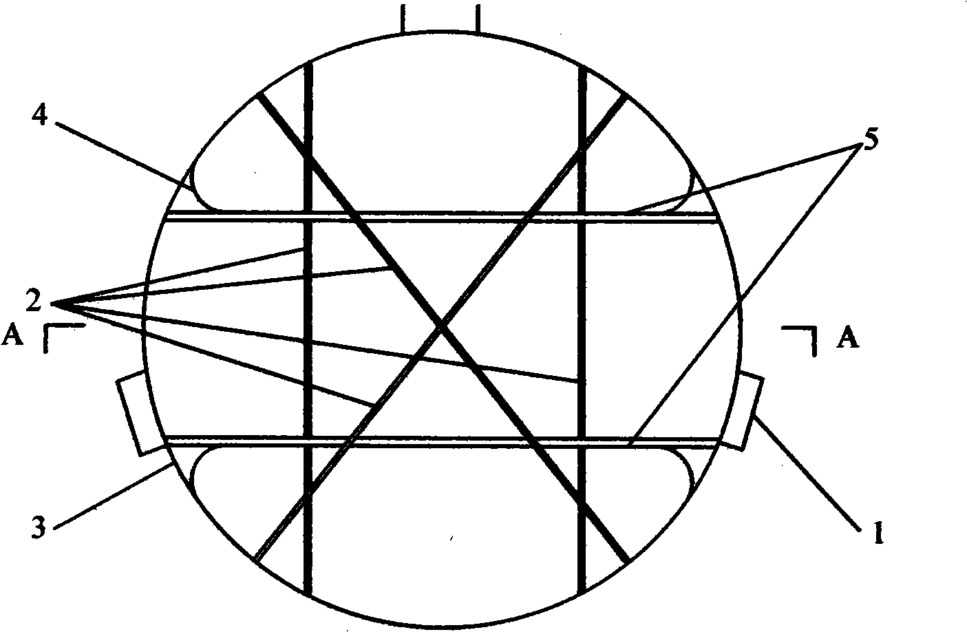
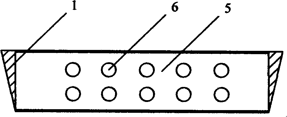
[0020] Such as figure 1 , 2 As shown in and 3, a magnet frame for plastic iron filings includes a frame body and support feet 1, the frame body is a protective ring 3 with upper and lower openings, and at least two parallel placement plates 5 are vertically fixed in the protective ring. A plurality of placement holes 6 for placing magnet rods are opened on the placement plate 5 according to requirements. The placement holes 6 are divided into upper and lower rows, and the placement holes 6 of the upper row and the lower row are evenly distributed in a staggered manner, and their apertures are slightly larger than the diameter of the magnet rods. , in order to disassemble the magnet bar. Of course, the number of magnet bars can also be adjusted according to product needs and requirements. One side of the protective ring 3 is provided with a dodge d...


PUM


Abstract

The invention relates to a device for separating iron filings mixed into nonmagnetic materials, in particular to a magnet frame for removing the iron filings from plastics. The magnet frame for removing the iron filings from the plastics comprises a frame body and supporting legs, and is characterized in that the frame body is a guard ring with an upside opening and an underside opening; placement plates which are used for laying magnetic rods and provided with placement holes are uniformly distributed on the surfaces of at least two plates which are vertically and fixedly arranged in the guard ring; and one side of the guard ring is provided with a movable door. The magnet frame has the advantages of simple structure and convenient use. With the structure, a plurality of magnetic rods are orderly arranged in layers, the magnet frame can fully adsorb the iron filings and can effectively prevent the magnetic rods from violently colliding with other objects, thereby protecting the magnetic rods, prolonging the service life of the magnetic rods, lowering production cost, reducing influence on the flow direction of the objects, guaranteeing blanking progress and improving production efficiency. In addition, as the joint part of the guard ring and the placement plates is fixedly provided with a transitional arc plate so as to eliminate dead angles, the magnet frame is easy to clean.

Description

technical field [0001] The invention relates to a device for separating iron filings mixed in non-magnetic materials, in particular to a magnet frame for removing iron filings from plastics. Background technique [0002] In the process of plastic production and processing, due to the wear and tear of equipment and unpredictable human factors, there are some iron powders in the premix, which will lead to unqualified product performance and bury a lot in the later use and processing of the product. Big hidden danger. Therefore, in production, when the product premix enters the next process, a special device is often used to absorb and remove the iron filings powder mixed in the mixture, which is referred to as overmagnetic. [0003] This special device for passing magnetism needs to meet two requirements: one is that it can fully absorb iron powder; the other is that it does not affect the normal feeding of the premix and flow to the next extrusion process. [0004] At prese...

Claims


Application Information

Patent Timeline
Patent Type & Authority Applications(China)
IPC IPC(8): B03C1/00
Inventor 吕卡利李国明林建华
Owner SHANGHAI KINGFA SCI & TECH
Why Eureka
Try Eureka