Apparatus and method for determining roll angle of a motorcycle

A roll angle, motorcycle technology, applied in the field of roll angle equipment, can solve the problem of increasing costs

Inactive Publication Date: 2009-04-08
KONINKLIJKE PHILIPS ELECTRONICS NV
View PDF1 Cites 5 Cited by
  • Summary
  • Abstract
  • Description
  • Claims
  • Application Information

AI Technical Summary

Problems solved by technology

This places high demands on the electronics of the gyro sensor and thus increases costs

Method used


Image

  • Apparatus and method for determining roll angle of a motorcycle
  • Apparatus and method for determining roll angle of a motorcycle
  • Apparatus and method for determining roll angle of a motorcycle

Examples


Embodiment Construction

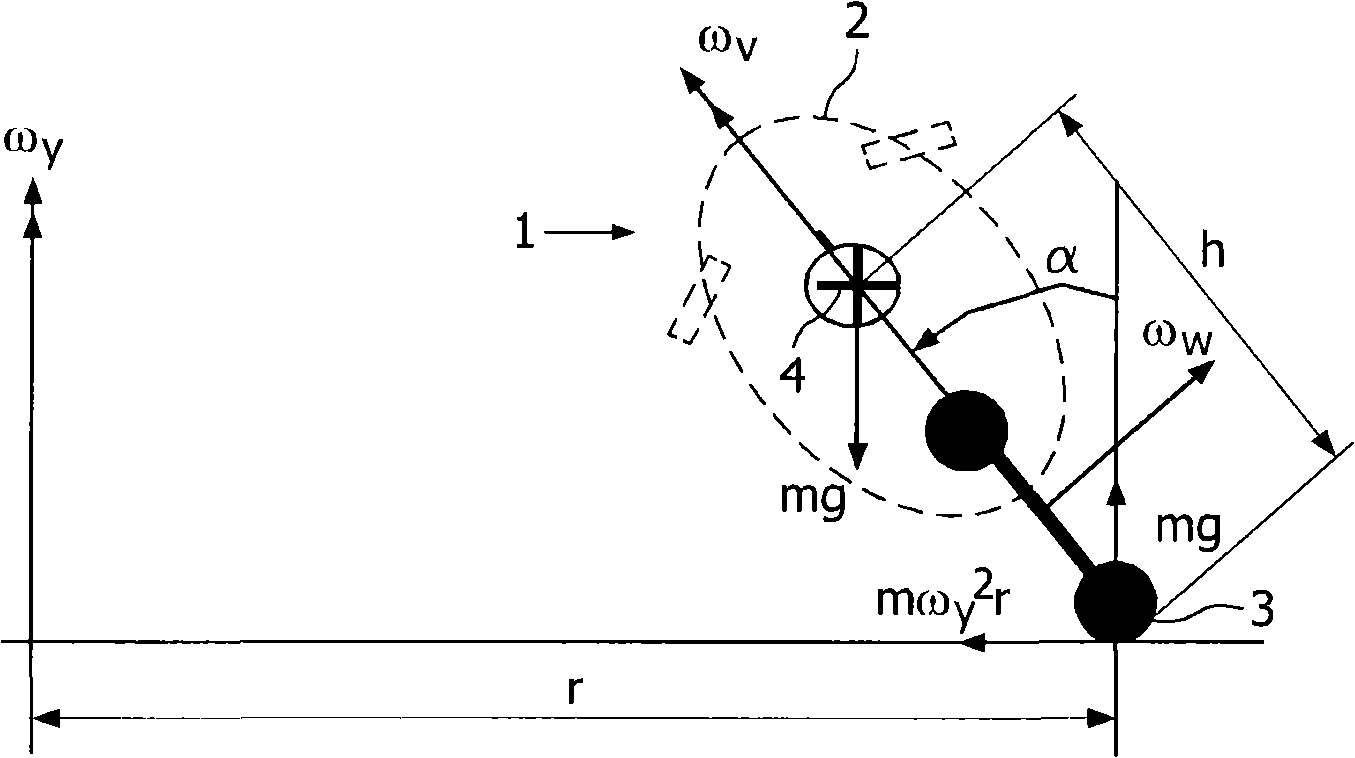
[0032] figure 1 is a view showing the motorcycle 1 when turning, which results in a roll angle α from the vertical. The body shell 2 of the motorcycle is indicated by dashed lines. The motorcycle 1 together with the driver has a center of gravity 4 which is at a height h above the underside of the wheels / tyres 3 . The gravitational force acting on the motorcycle is represented by the vector mg. A turn with radius r results in vector ω y Indicates the yaw rate. The rotational speed of one of the 3 wheels of the motorcycle is given by the vector ω w express.

[0033] According to a preferred embodiment of the present invention, two methods are used to determine the roll angle, namely by roll rate and by yaw rate. These methods are based on the availability of roll rate and yaw rate from the respective gyroscopes, which are described in detail below.

[0034] With the first method, a first intermediate value of the roll angle α is determined by integrating the signals of t...


PUM


Abstract

An apparatus for determining roll angle of a motorcycle (1) as when taking a curve or bend in a road. The apparatus includes a first gyro sensor (11) that provides a roll rate signal, a second gyro sensor (12) that provides a yaw rate signal, and a velocity sensor (36). The apparatus is configured to integrate the roll rate signal to obtain a first intermediate roll angle value and to determine a second intermediate roll angle value from the yaw rate and the vehicle velocity. The apparatus combines the two intermediate roll angle values into an output value for the roll angle that can be used by a servo (50) to adjust the orientation of the headlamp so that the beam pattern remains leveled with the horizon when the motorcycle (1) rolls when taking a curve.

Description

technical field [0001] The invention relates to a device for determining the roll angle of a motorcycle when turning or turning on a road. More particularly, the present invention relates to an apparatus for use with motorcycle headlights to automatically maintain the beam pattern horizontally in the face of changes in vehicle roll angle relative to ground level. Furthermore, the invention relates to software and a method for determining the roll angle. Background technique [0002] Motorcycle headlights have a beam pattern shaped according to legal requirements to illuminate the road ahead without blinding oncoming traffic. When aligned with the ground plane, this mode is suitable for all requirements. However, when the motorcycle turns to steer, the range of the beam on the inside of the turn is greatly reduced, which poses a safety risk because the driver cannot see objects on the road ahead, while the beam on the outside of the turn Dazzles oncoming traffic. These pr...

Claims


Application Information

Patent Timeline
Patent Type & Authority Applications(China)
IPC IPC(8): B60T8/17B60T8/172
CPCB60Q1/12B60Q2300/112B62J6/02B60Q2300/134B60T2230/03B60T8/1706B60T8/172B60Q2300/136B62J6/023B62J45/4151
Inventor F·G·P·彼得斯H·M·W·古森斯H·G·J·J·A·夫鲁门
Owner KONINKLIJKE PHILIPS ELECTRONICS NV
Why Eureka
Try Eureka