
Load-sensitive and logical double-pump switching valve structure

A load-sensitive switching valve technology, applied in the field of hydraulic valves, can solve the problems of increasing manufacturing costs, increasing the complexity of linkage control, and being unfavorable for popularization, and achieves the effects of reasonable design principles, convenient loading, and simple structure

Active Publication Date: 2011-04-20
卢宇
View PDF0 Cites 0 Cited by
  • Summary
  • Abstract
  • Description
  • Claims
  • Application Information

AI Technical Summary

Problems solved by technology

Electric on-off switch, hydraulic control pipeline and electrical circuit need to be laid externally, which not only increases the manufacturing cost, but also increases the complexity of linkage operation, which is not conducive to popularization

Method used


Image

  • Load-sensitive and logical double-pump switching valve structure
  • Load-sensitive and logical double-pump switching valve structure
  • Load-sensitive and logical double-pump switching valve structure

Examples


Embodiment Construction

[0025] The present invention will be further described in detail below in conjunction with the accompanying drawings and embodiments.

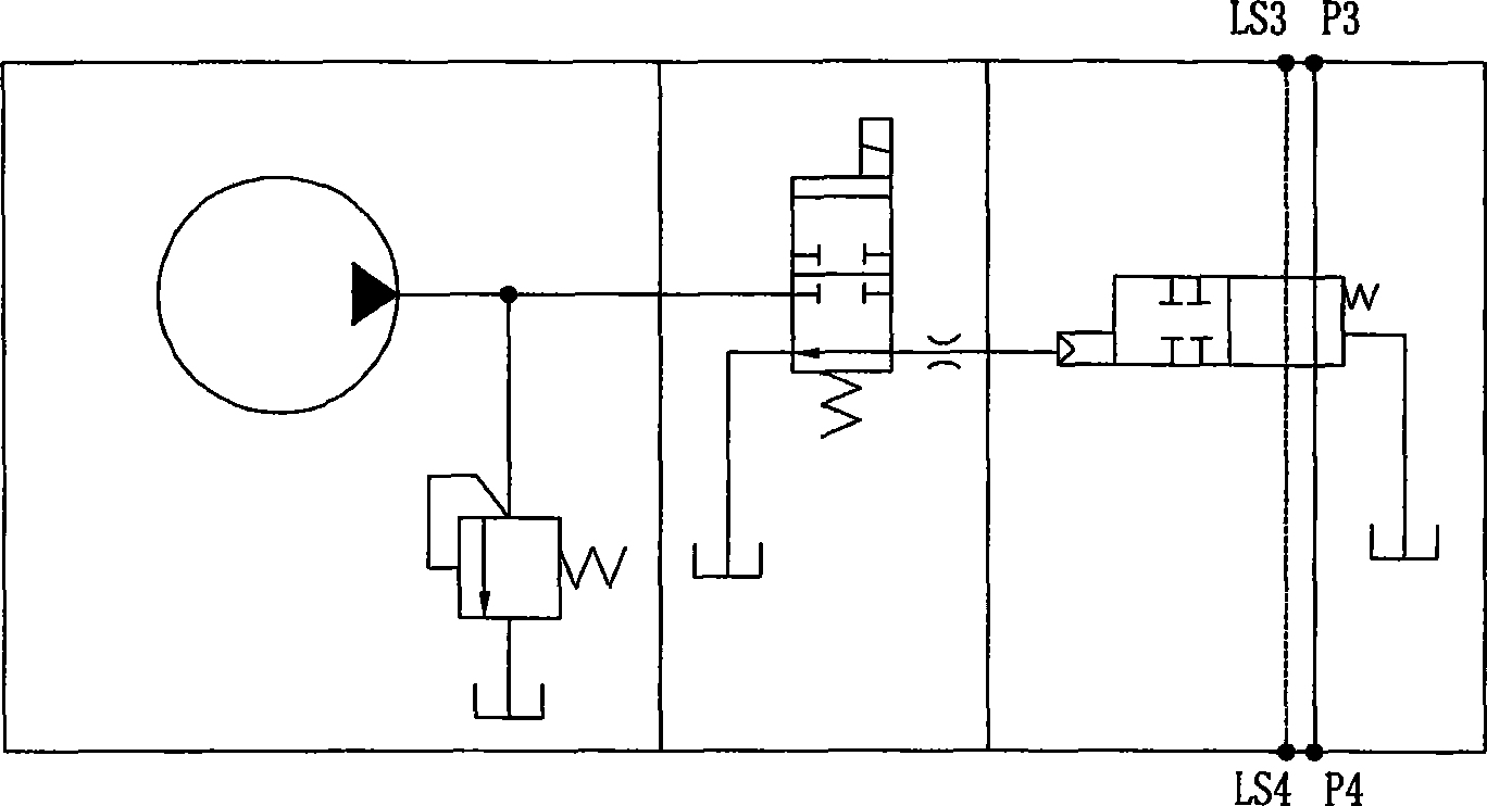
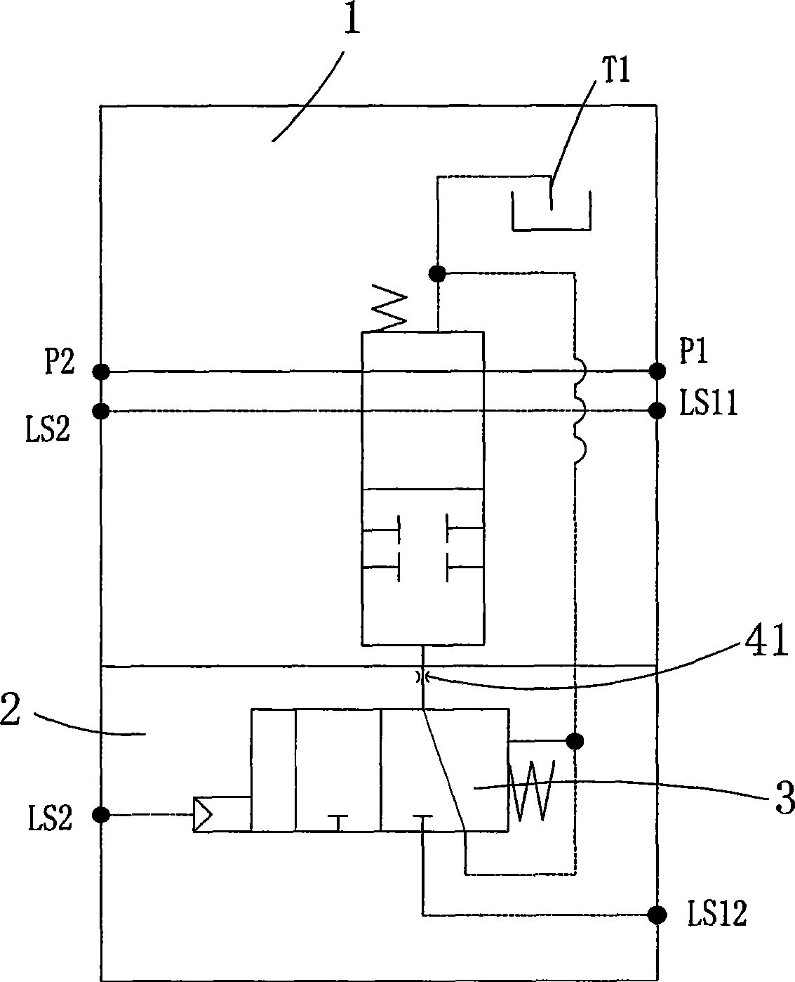
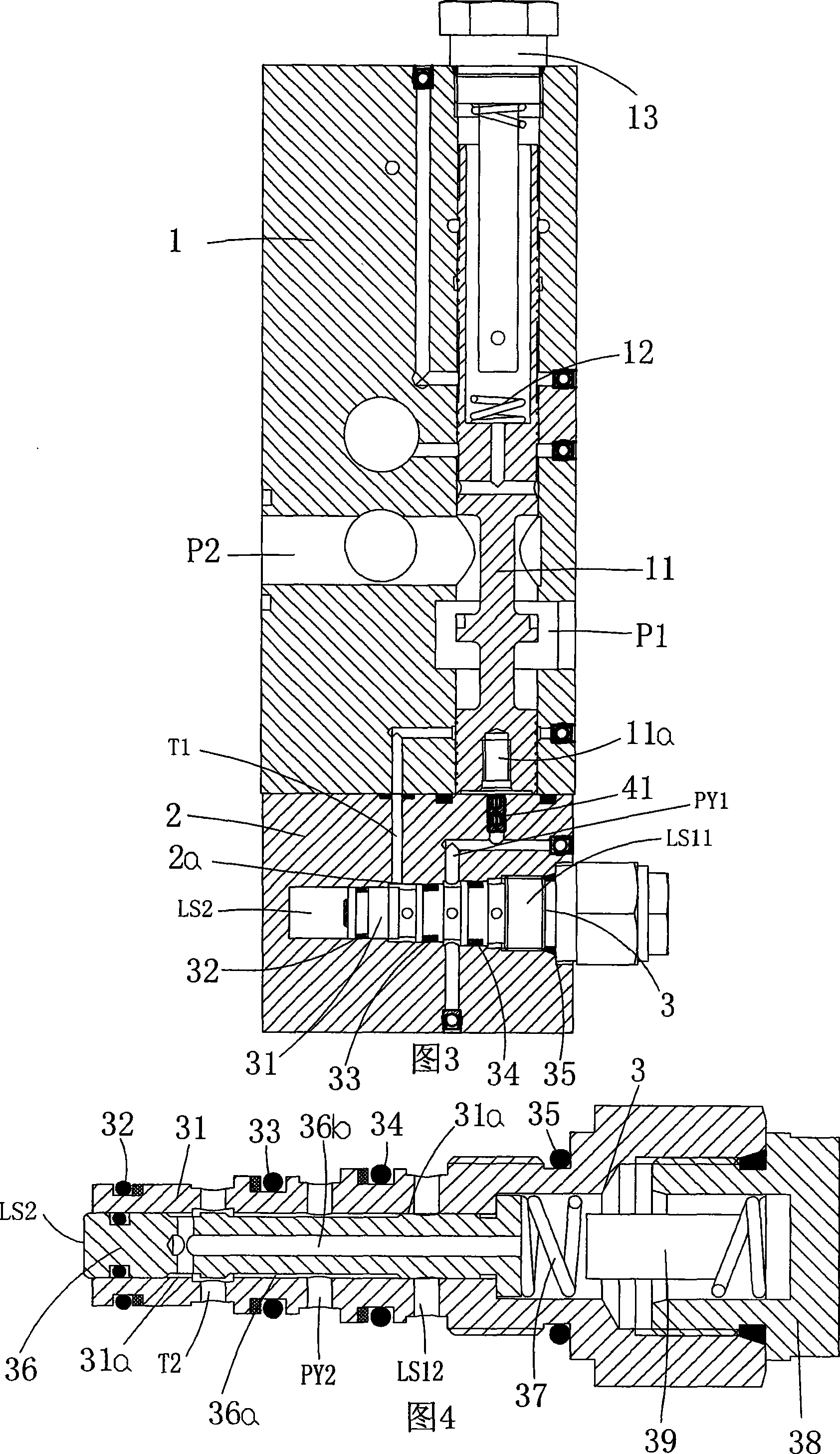
[0026] Such as figure 2 As shown in Figure 6, the reference numbers are as follows: the first valve body 1, the switching valve core 11, the hydraulic control chamber 11a, the first spring 12, the screw plug 13, the second valve body 2, the first slideway hole 2a, the logic Valve 3, valve sleeve 31, second slideway hole 31a, first sealing ring 32, second sealing ring 33, third sealing ring 34, fourth sealing ring 35, logic valve core body 36, ring groove body 36a, middle Hole 36b, second spring 37, second spring seat 38, spring support seat 39, transition block 4, damper 41, first control spool 5, third spring 51, first drive chamber 52, first hydraulic control hole 53, the second control spool 6, the fourth spring 61, the second drive chamber 62, the second hydraulic control hole 63, the main control port LS1, the first input control port L...


PUM


Abstract

The invention discloses a dual-pump switch valve structure which loads sensitive logic; which comprises a valve body and a valve core which are matched with each other; the valve body is provided with a first pressure cavity which is communicated with a first oil pump and a second pressure cavity which is communicated with a second oil pump; a switch valve core which can control the on and off ofthe oil circuits of the first pressure cavity and the second pressure cavity is arranged in the valve body in a sliding way, and a fluid control cavity is arranged at the bottom end of the switch valve core; the valve body is respectively provided with a first input control port, a driving control port, a first output control port, and a first oil return pore, wherein, the first output control port is communicated with the fluid control cavity; a logic valve is arranged in the calve body in a sliding way and the logic valve can simultaneously control the on and off of the first input control port and the first output control port, and the on and off of the driving control pore and the first oil return pore; a second valve body is arranged at the bottom end of a first valve body; the fluidflow of the logic valve can control the transposition of the switch valve core; and the function update of original products can be achieved by only overlapping one second valve body on the original first valve body, and the loading is convenient and fast.

Description

technical field [0001] The invention relates to the technical field of hydraulic valves, in particular to a structure of a load-sensitive logic double-pump switching valve. Background technique [0002] Most of the control valve groups of land-based hydraulic steam cranes and belt-covered cranes adopt proportional control stepless speed regulation technology. In order to improve work efficiency, double oil pumps are used to directly merge to speed up the movement speed of hoisting, luffing and telescopic movement. However, in the process of operation, it is often necessary to operate in conjunction with hoisting and luffing or hoisting and telescopic, and when the diesel engine is driving the oil pump at idle speed, the combined flow rate is also low. At this time, it will cause the problem of oversaturation of the oil pump flow, especially in the linkage operation. When the two load pressures are very different, the heavy-duty actuator in the linkage cannot get oil supply,...

Claims


Application Information

Patent Timeline
Patent Type & Authority Patents(China)
IPC IPC(8): F15B13/02
Inventor 卢宇
Owner 卢宇
Learn More