
Fully pre-mixing gas combustion burner device

A gas burner and burner technology, applied in the direction of gas fuel burners, burners, combustion methods, etc., can solve the problems of unfavorable environmental protection, uneven flame, unreasonable premix chamber structure design, etc., and achieve enhanced efficiency and reduced The effect of outer surface temperature, flame uniformity and stability

Active Publication Date: 2013-05-22
GUANGDONG MACRO GAS APPLIANCE
View PDF2 Cites 3 Cited by
  • Summary
  • Abstract
  • Description
  • Claims
  • Application Information

AI Technical Summary

Problems solved by technology

This invention adopts a no-nozzle, fully premixed combustion structure, which can improve the combustion efficiency of the burner and reduce the cost of the burner. However, the structural design of the premixed chamber of the invention is unreasonable, and the open end of the spoiler behind the multi-microporous combustion body The gas pressure is greater than that of the closed end, which makes the gas pressure inconsistent and causes uneven flame, which is easy to produce CO and NOx, which is not conducive to environmental protection

Method used


Image

  • Fully pre-mixing gas combustion burner device

Examples


specific Embodiment 1

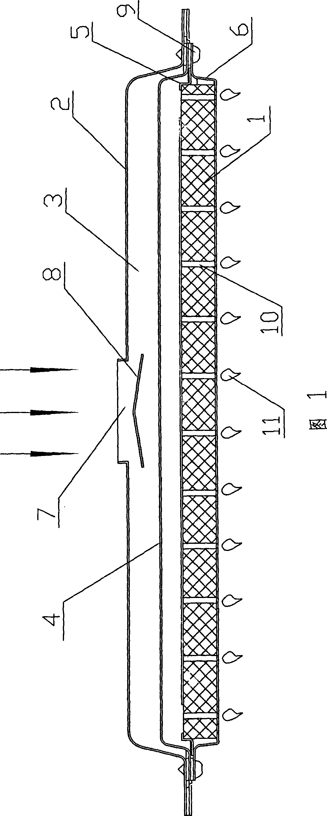
[0020] Specific embodiment one: as figure 1 As shown, this embodiment includes a burner 1 and a fixing device for installing the burner 1. The periphery of the burner 1 is provided with an air-mixing chamber 3 formed by a casing 2, and between the burner 1 and the casing 2 is a The pressure dividing partition 4 has a gap between the pressure dividing partition 4 and the casing 2 . The pressure dividing partition 4 is a plate-shaped structure with a plurality of small holes distributed thereon. The diameter of the small hole away from the air inlet 7 on the pressure dividing partition 4 is equal to the diameter of the small hole close to the air inlet 7 . The fixing device includes a fixed frame 6 and a fixed plate 5, the fixed frame 6 is a frame structure, the fixed plate 5 is a right-angled strip structure, the right-angled side of the fixed plate 5 is lapped on the edge of the burner 1, and the fixed frame 6 is relatively screwed and The burner 1 is fastened on the fixed f...

specific Embodiment 2

[0021] Specific embodiment two: the difference between the present embodiment and embodiment one is that there is no splitter plate 8 under the air inlet 7, and the diameter of the small hole away from the air inlet 7 on the pressure divider 4 is greater than the diameter of the small hole near the air inlet 7 , except for these two differences, other structures and implemented functions are consistent with Embodiment 1.

[0022] In the technical solution of the present invention, the size of the small holes of the pressure dividing partition can be the same, and corresponding changes can also be made according to the wind pressure. Larger holes are opened in places where the wind pressure is small, and holes are opened in places where the wind pressure is high. It will be smaller; if the air inlet is small, a splitter plate will be installed at the air inlet to avoid the wind pressure at this place from being higher than other places. If the air inlet is larger, there is no ne...


PUM


Abstract

The invention discloses a fully premixed gas burner device which comprises a burner and a fixation device used for fixing the burner, wherein, the periphery of the burner is provided with a gas mixing cavity formed by an encloser; a partial pressure baffle with a hole is arranged between the burner and the encloser; and a clearance is left between the partial pressure baffle and the encloser. Thefully premixed gas burner device has the advantages of not only simple structure and convenient installation and maintenance, but also high combustion efficiency and stable flame, and remarkably reduces the contents of CO and NOx in flue gas.

Description

technical field [0001] The invention relates to the technical field of gas water heaters for household appliances, and more specifically relates to a fully premixed gas burner device. Background technique [0002] At present, in the field of gas water heater technology, fully premixed condensing gas water heaters are more and more accepted by consumers due to their many advantages such as energy saving and environmental protection. Therefore, there are more and more researches on the burner as its key component. For example, the application number is CN200520063252 .5, the application date is 2005.08.23, the patent name is a utility model of a fully premixed gas water heater burner, the patent discloses a fully premixed gas water heater burner, which is composed of multiple combustion units, each A combustion unit includes a burner head, a cavity and a nozzle, the burner head communicates with the cavity, a mixing tube is arranged on the cavity, the nozzle is located at the ...

Claims


Application Information

Patent Timeline
Patent Type & Authority Patents(China)
IPC IPC(8): F23D14/02
Inventor 余少言仇明贵胡定刚向熹李瑞丰陈哲
Owner GUANGDONG MACRO GAS APPLIANCE
Learn More