Splicer with rotatable splicing cassette carrier

An adapter and bracket technology, which is applied in the field of mobile or portable lightweight adapters, can solve the problems of bulky device design and increased weight, and achieve the effect of saving weight

Inactive Publication Date: 2009-03-25
CCS TECH INC
View PDF0 Cites 4 Cited by
  • Summary
  • Abstract
  • Description
  • Claims
  • Application Information

AI Technical Summary

Problems solved by technology

However, for ergonomic reasons, the device must be designed to be le

Method used


Image

  • Splicer with rotatable splicing cassette carrier
  • Splicer with rotatable splicing cassette carrier
  • Splicer with rotatable splicing cassette carrier

Examples


Embodiment Construction

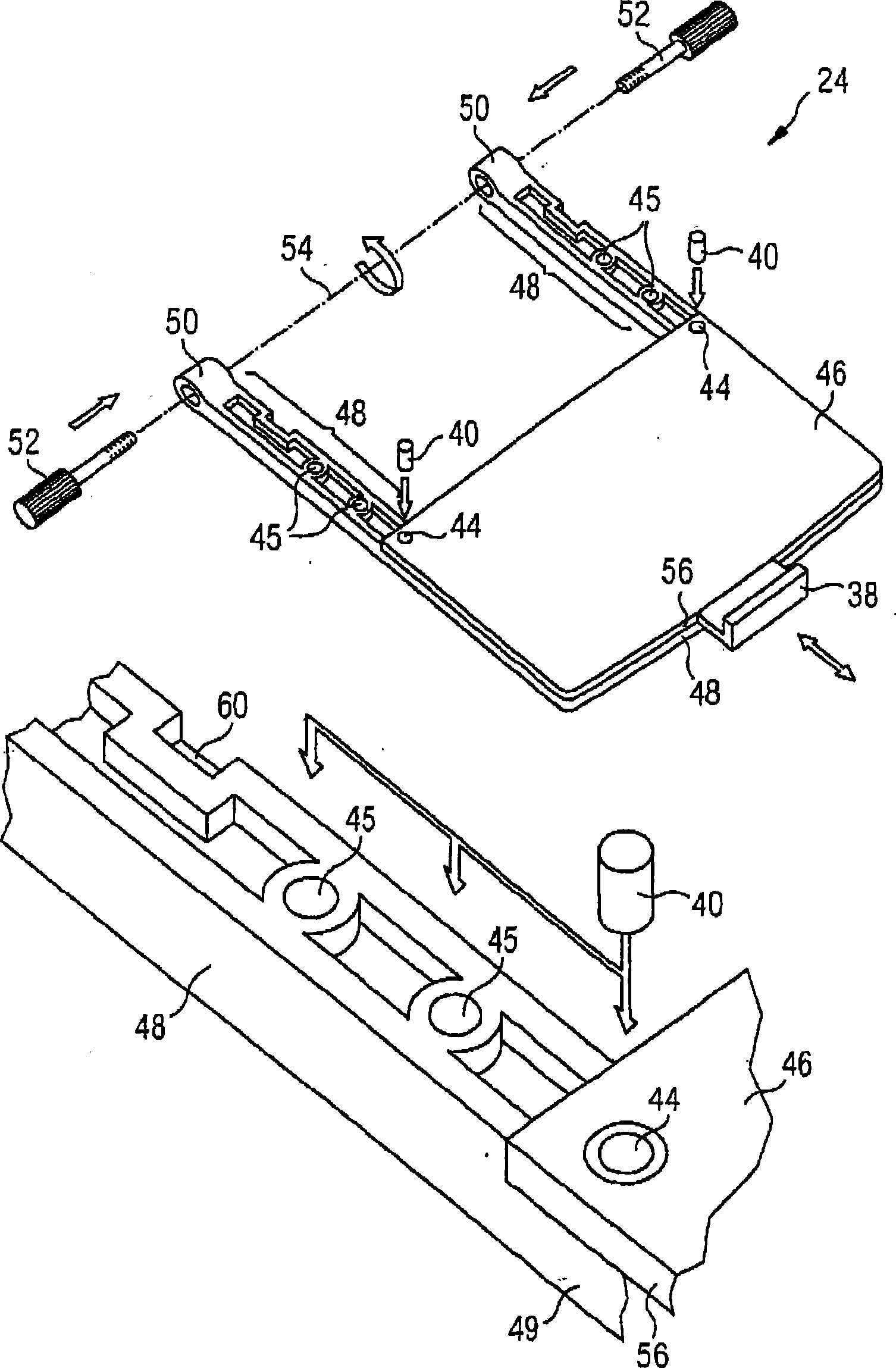
[0036] figure 1 A perspective view of a splice box bracket 24 is shown in accordance with an exemplary embodiment of the present invention. The upper part of figure can see the integral body of junction box bracket 24, and figure 1 Shown in the lower half of is an enlarged detail view of the carriage arm 48 .

[0037] The splice box bracket 24 includes a plate 56 that has a planar surface 46 and may be made of metal or plastic, for example. Plate 56 is used to accommodate junction box 36 (see Figure 5 ). The splice box bracket 24 also has two bracket arms 48 that extend the flat surface 46 of the plate 56 beyond its edge. Carriage arm 48 has two functions. On the one hand, they stabilize the plate 56 by means of elements 49 extending below it, thereby ensuring a stable position of the metal plate at a given angle of rotation and preventing twisting; on the other hand, they connect the metal plates To bush 50 , which is part of the shaft on which splice box bracket 24 ...


PUM


Abstract

A splicer (20) comprises a chassis (22) with an opening, in which a splicing unit (10) for splicing optical waveguides (18) is arranged. The splicer can be controlled using a control and display apparatus (26). A splicing cassette carrier (24) is arranged on the chassis (22) such that it can rotate. The splicing cassette carrier is designed such that it can be used both for fixing a splicing cassette but also as a carrying handle for the splicer. The splicer furthermore has a control unit (34) via which the splicer is switched into an active operational state or a stand-by mode, depending on the rotation position (71, 73) of the splicing cassette carrier. If the splicing cassette carrier is open, a light intensity of a background illumination of the display apparatus (26) and a light intensity of an illumination device (63) can be controlled in a variable manner. On account of the reduced power consumption associated therewith, it is possible to extend the operational readiness of the splicer.

Description

technical field [0001] The present invention relates to a splice having a splice box carrier that functions to hold the splice box when an optical waveguide or optical fiber is spliced ​​in the splice. The present invention also relates to a mobile or portable portable splicer which can be transported and used by an operator to splice optical fibers inside or outside an enclosed building. Background technique [0002] Although splices are particularly suitable for splicing optical waveguides and optical fibers, splices can also be used in a wide variety of technical fields. Mobile splicers are especially suitable for use in the field and can be used, for example, when fibers are spliced ​​on antenna masts or underground cables. Mobile adapters such as these generally comprise an engagement unit, a control and display unit, a retraction unit and a chassis housing these units. The splicer usually has an attached splice box bracket to accommodate the splice box required for s...

Claims


Application Information

Patent Timeline
IPC IPC(8): G02B6/255
Inventor M·弗兰扎T·德特珀H·克隆威特C·海德勒M·克拉R·考萨特
Owner CCS TECH INC
Why Eureka
Try Eureka