Spherical surface hole boring and milling mechanism

A technology of boring, milling and inner hole, applied in milling machine equipment, boring/drilling device, details of milling machine equipment, etc., can solve the problems of product processing efficiency and quality reduction, spherical contour error, product cost increase, etc., to save equipment investment cost , The effect of reducing spherical contour error and improving efficiency

Inactive Publication Date: 2012-09-05
HUZHOU MACHINE TOOL WORKS
View PDF0 Cites 0 Cited by
  • Summary
  • Abstract
  • Description
  • Claims
  • Application Information

AI Technical Summary

Problems solved by technology

[0002] In the prior art, special-purpose machine tools are used for the boring and milling of the spherical inner hole. Because the spherical surface processing requires high precision, accurate tool movement and control of the cutting amount, it is difficult for ordinary machine tools to do this, and at the same time requires the operator to have a good advanced operating technology and experience, but the use of special machine tools for processing requires large investment and increased product costs, which is not conducive to the development of enterprises
There is also a kind of CNC machining. For example, in the process of machining 300MW generator set, the inner spherical bearing bush hole of the motor end and valve adjustment end spindle bearing on the model H165 low-pressure outer cylinder, the spherical diameter is φ985mm, and the roughness is 0.8um. At present, the FA-C221 3-axis linkage CNC boring and milling machine manufactured by Italy INNSA company is used for processing. Although the CNC machine tool is used, the tool trajectory error of the multi-axis CNC servo motor composite forming will cause spherical contour errors, resulting in product processing efficiency and reduced quality

Method used


Image

  • Spherical surface hole boring and milling mechanism
  • Spherical surface hole boring and milling mechanism
  • Spherical surface hole boring and milling mechanism

Examples


Embodiment Construction

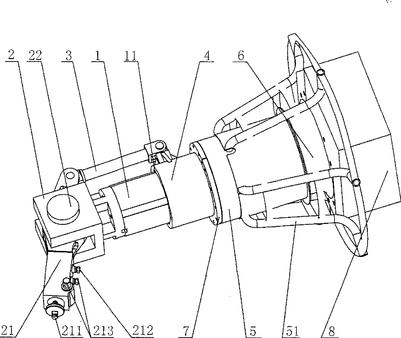
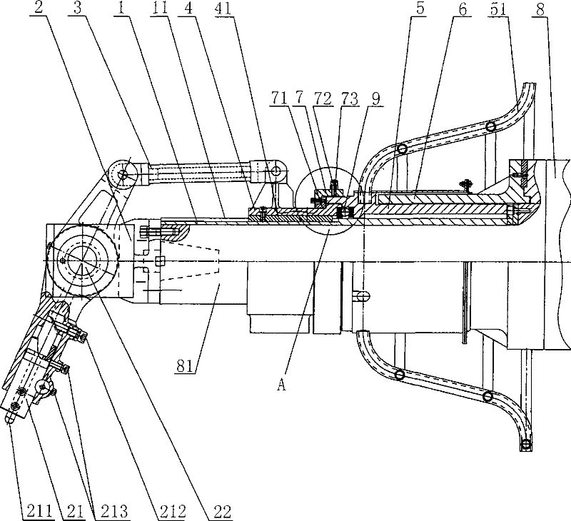
[0018] Such as figure 1 , figure 2 The spherical inner hole boring and milling mechanism of the present invention as shown includes a main shaft 81, the main shaft 81 is covered with a main shaft connecting sleeve 1, the front end of the main shaft 81 is provided with a tool holder disc 2, a tool holder 21 is installed in the tool holder disc 2, and a tool holder 21 is provided on the tool holder 21. The pin shaft 22 of the integral structure with the knife rest 21, the knife rest 21 is transferred on the knife rest disc 2, the knife 211 is installed at the front end of the knife rest 21 and is equipped with a cutter fine-tuning nut 212 and a cutter lock nut 213, and the cutter fine-tuning nut 212 tail The tail end of the tool is arranged as an inclined plane that cooperates with each other, the rotation of the tool fine-tuning nut 212 controls the expansion and contraction of the tool 211 , and the tool locking nut 213 is used to fix the tool 211 . The tail end of the tool ...


PUM


Abstract

The invention discloses a sphere inner hole milling and boring mechanism, which comprises a main shaft, a main shaft connecting sleeve is nested at the outside of the main shaft, a tool post disc is arranged at the front end of the main shaft, a tool post is connected in the tool post disc rotationally, a linkage mechanism is connected at the tail end of the tool post rotationally, and the other end of the linkage mechanism is fixedly connected with a circular sleeve, the rear end of the circular sleeve is connected with a feeding mechanism, the circular sleeve is nested on the main shaft connecting sleeve axially and glidingly, and rotates with the main shaft connecting sleeve by linkage. The sphere inner hole milling and boring mechanism can be arranged on rams and main shafts of commonfloor-type milling and boring machines and gantry type milling machines, and has relative low tool path error and spherical contour error when in uni-axial and co-diametric tool feeding; and the invention takes the rotation of the sphere main shaft as the main motion, and the feeding mechanism realizes the auxiliary motion, the combination of the motions improves the boring efficiency, the spherical surface precision is up to standard, the machine tool utilization rate is increased, the production loads of high-precision machine tools are released, and the input costs of equipment are greatlysaved.

Description

technical field [0001] The invention relates to a machining device, in particular to a spherical inner hole boring and milling mechanism mounted on a milling machine. Background technique [0002] In the prior art, special-purpose machine tools are used for the boring and milling of the spherical inner hole. Because the spherical surface processing requires high precision, accurate tool movement and control of the cutting amount, it is difficult for ordinary machine tools to do this, and at the same time requires the operator to have a good However, the use of special machine tools for processing requires large investment and high product costs, which is not conducive to the development of enterprises. There is also a kind of CNC machining. For example, in the process of machining 300MW generator set, the inner spherical bearing bush hole of the motor end and valve adjustment end spindle bearing on the model H165 low-pressure outer cylinder, the spherical diameter is φ985mm,...

Claims


Application Information

Patent Timeline
Patent Type & Authority Patents(China)
IPC IPC(8): B23B43/00B23C3/02B23Q5/22
Inventor 张宁一
Owner HUZHOU MACHINE TOOL WORKS
Why Eureka
Try Eureka