
Steam generator tube, method of manufacturing the same and once-through steam generator

一种蒸汽发生器、形式的技术,应用在内型面的蒸汽发生器管领域,能够解决螺旋带得不到冷却、阻挡、不适用运行条件等问题,达到小压力损失的效果

Active Publication Date: 2009-03-18
SIEMENS ENERGY GLOBAL GMBH & CO KG
View PDF0 Cites 8 Cited by
  • Summary
  • Abstract
  • Description
  • Claims
  • Application Information

AI Technical Summary

Problems solved by technology

However, these hitherto known internals have the common disadvantage that on the one hand they block the (originally) free cross-section in the center of the tube and on the other hand they deflect the overall flow significantly and in this case local "over-swirl". (überdrallen)”
Simple helical bands, e.g. in the case of a higher steam content in a two-phase flow, lead to an accumulation of the water phase while drying in the triangular zone between the pipe wall and the helical bands and thus to an underutilization of the inner wall area on the shaded side of the helical bands. cooling
Steam generator tubes with internals in the form of helical bands are therefore also not suitable for all operating conditions normally found in steam generators

Method used


Image

  • Steam generator tube, method of manufacturing the same and once-through steam generator
  • Steam generator tube, method of manufacturing the same and once-through steam generator
  • Steam generator tube, method of manufacturing the same and once-through steam generator

Examples


Embodiment Construction

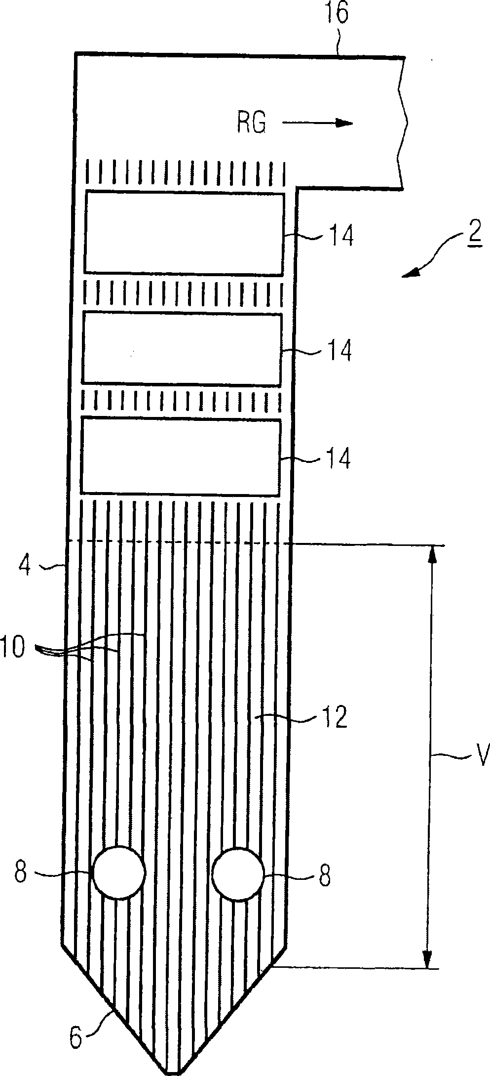
[0029] exist figure 1 A straight-through steam generator 2 with a rectangular cross section is schematically shown in , the vertical gas channel of which is formed by a surrounding wall or combustion chamber wall 4 , which transitions at the lower end into a bucket-shaped bottom 6 .

[0030] A number of burners for the fuel in openings 8 (only two are visible in the figure) are arranged in the combustion chamber wall 4 composed of steam generator tubes 10 in the ignition region V of the gas duct. The vertically arranged steam generator tubes 10 are gas-tightly welded to one another in the ignition region V to form the evaporator heating surface 12 .

[0031] Above the ignition region V of the air duct is a convective heating surface 14 . Located above it is a flue outflow channel 16 through which flue gas RG produced by burning fossil fuel leaves the vertical flue. The flow medium flowing in the steam generator tube 10 is heated by the radiant heat of the burner flame and th...


PUM


Abstract

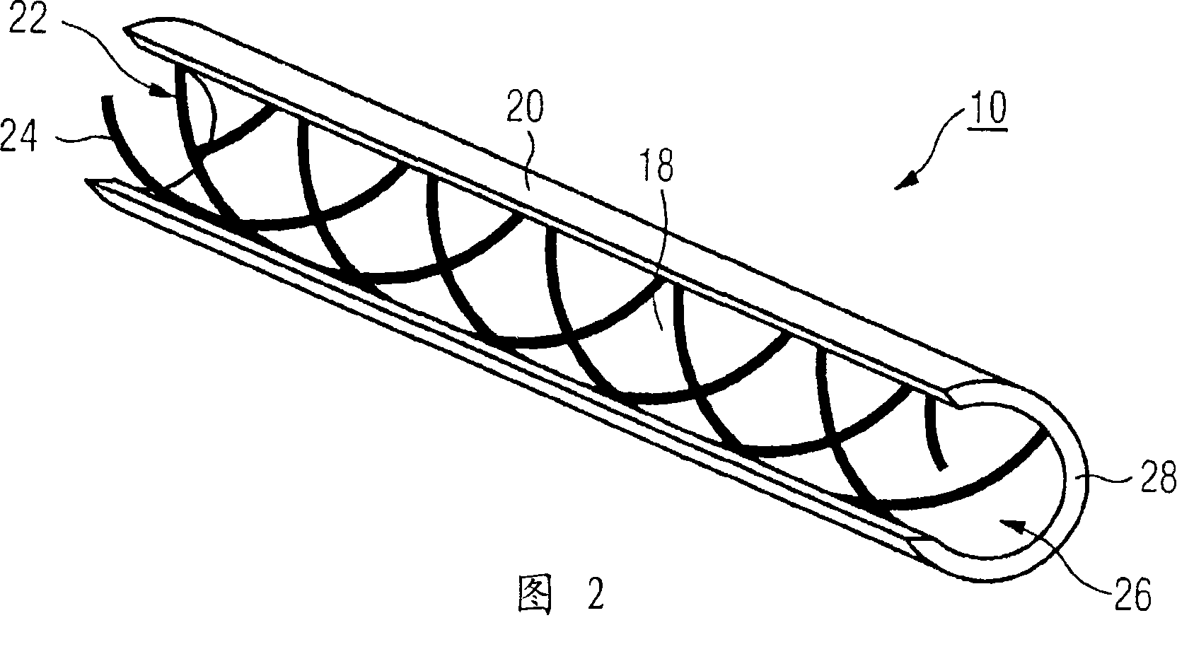
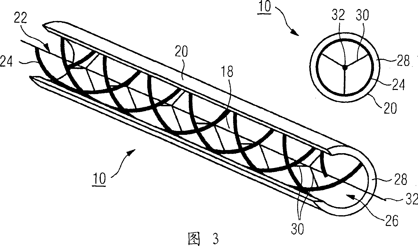
The invention relates to a steam generator pipe (10) which can be produced in a simple and economical manner and which has particularly good heat transitional behaviour having a large band width with various operational conditions. According to the invention, at least one insert (22) is arranged in the inner chamber of the pipe (18) in order to form a swirl-generating inner profile. The insert (22) comprises a plurality of wires (24) which wind, in a screw-like manner, along on the inner wall of the pipe (26) in the form of a multi-path thread.

Description

technical field [0001] The invention relates to a steam generator tube with a swirl-forming inner profile. Furthermore, the invention relates to a method for producing a steam generator tube provided with a swirl-forming inner profile. Background technique [0002] In the combustion chamber wall of a straight-through steam generator, steam generator tubes which are gas-tightly welded to one another via webs are usually used to form gas channels surrounding the flame space which are connected in parallel for the flow medium to flow through. Instead of flat iron webs located between the steam generator tubes, it is also possible to use tubes which have already been provided by the manufacturer with shaped cooling fins. In this case the steam generator tubes can be arranged vertically or obliquely. In order to ensure a reliable operating behavior of the straight-through steam generator, the steam generator tubes are usually designed in such a way that sufficient cooling of th...

Claims


Application Information

Patent Timeline
Patent Type & Authority Applications(China)
IPC IPC(8): F22B37/18F22B29/06
CPCF22B37/18F22B29/06
Inventor 乔基姆·弗兰克奥利弗·赫布斯特霍尔格·施米特
Owner SIEMENS ENERGY GLOBAL GMBH & CO KG
Learn More