
Emergency environmental radiation monitoring system

An environmental radiation and monitoring system technology, applied in the field of environmental radiation monitoring system, can solve the problems of high noise, low work efficiency, unstable operation of system equipment, etc., and achieve the effect of small economic cost and fast response

Inactive Publication Date: 2009-03-18
CHINA GENERAL NUCLEAR POWER CORP +1
View PDF0 Cites 16 Cited by
  • Summary
  • Abstract
  • Description
  • Claims
  • Application Information

AI Technical Summary

Problems solved by technology

[0002] The old emergency environmental monitoring vehicle is equipped with G-M type gamma radiation detector, NaI gamma spectrometer, air sampling pump, portable generator and power supply. During the use, the inventor found that due to design defects, the old system has mainly There are problems in the following aspects: the generator is slow to start by manpower, and the noise is loud, the system equipment is not stable, and there are frequent failures, and the system availability is low
In particular, the monitoring vehicle does not have the functions of automatic positioning monitoring and real-time data transmission. It can only rely on manual positioning monitoring and manual reporting of monitoring data, and the work efficiency is low.
The single voice communication method makes it impossible for the monitoring vehicle to report data to the emergency headquarters after entering the "blind zone", and the monitoring vehicle loses contact with the emergency headquarters completely
Since the emergency environmental radiation monitoring system and monitoring software have not been established, it is difficult for the emergency command center to obtain the data of the monitoring vehicle in time under the accident state, and it is impossible to monitor the spread of the radioactive plume of the power station and the impact on the surrounding environment in real time.

Method used


Image

  • Emergency environmental radiation monitoring system
  • Emergency environmental radiation monitoring system
  • Emergency environmental radiation monitoring system

Examples


Embodiment Construction

[0026] In order to make the object, technical solution and advantages of the present invention clearer, the present invention will be further described in detail below in conjunction with the accompanying drawings and embodiments. It should be understood that the specific embodiments described here are only used to explain the present invention, not to limit the present invention.

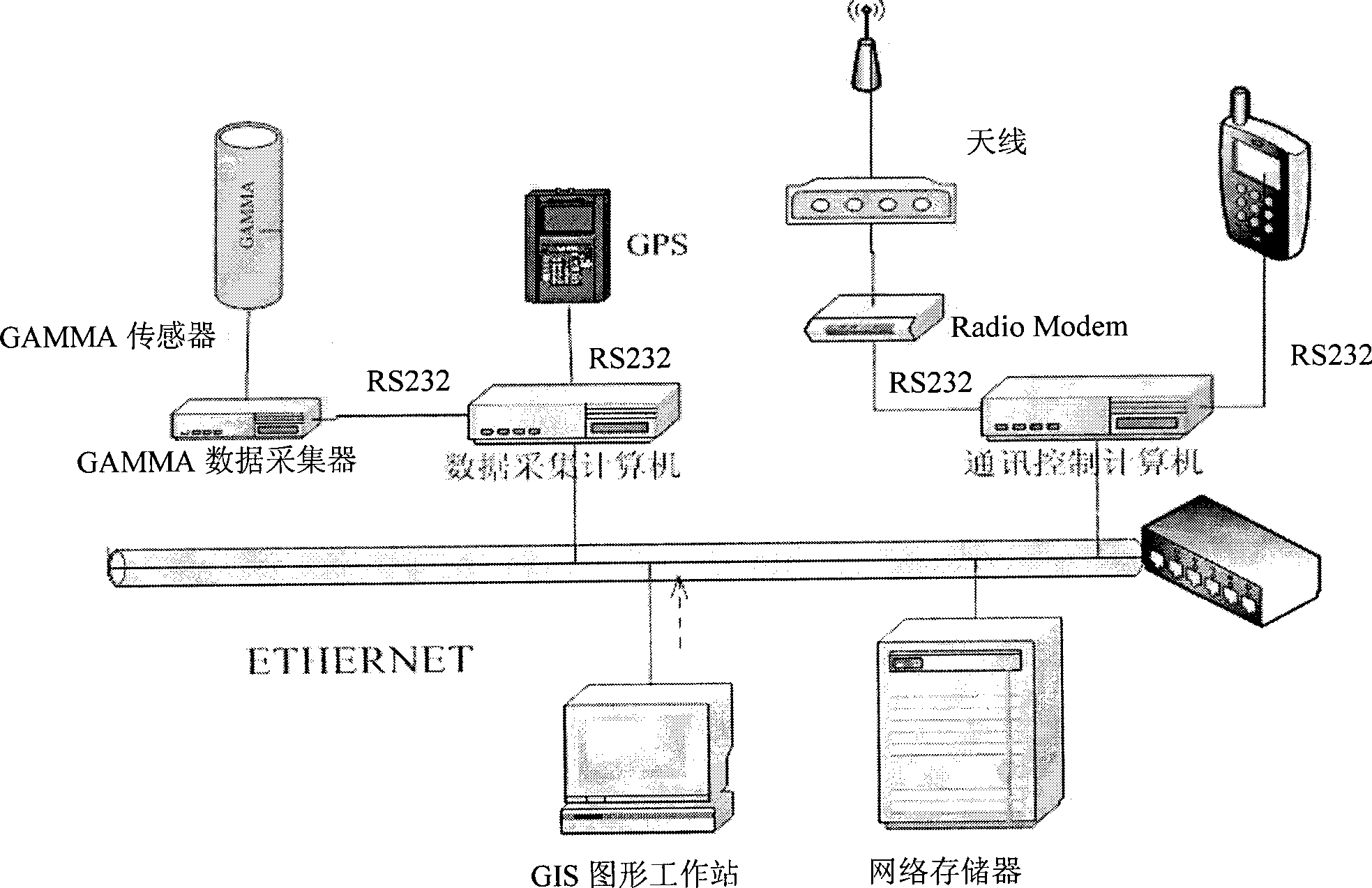
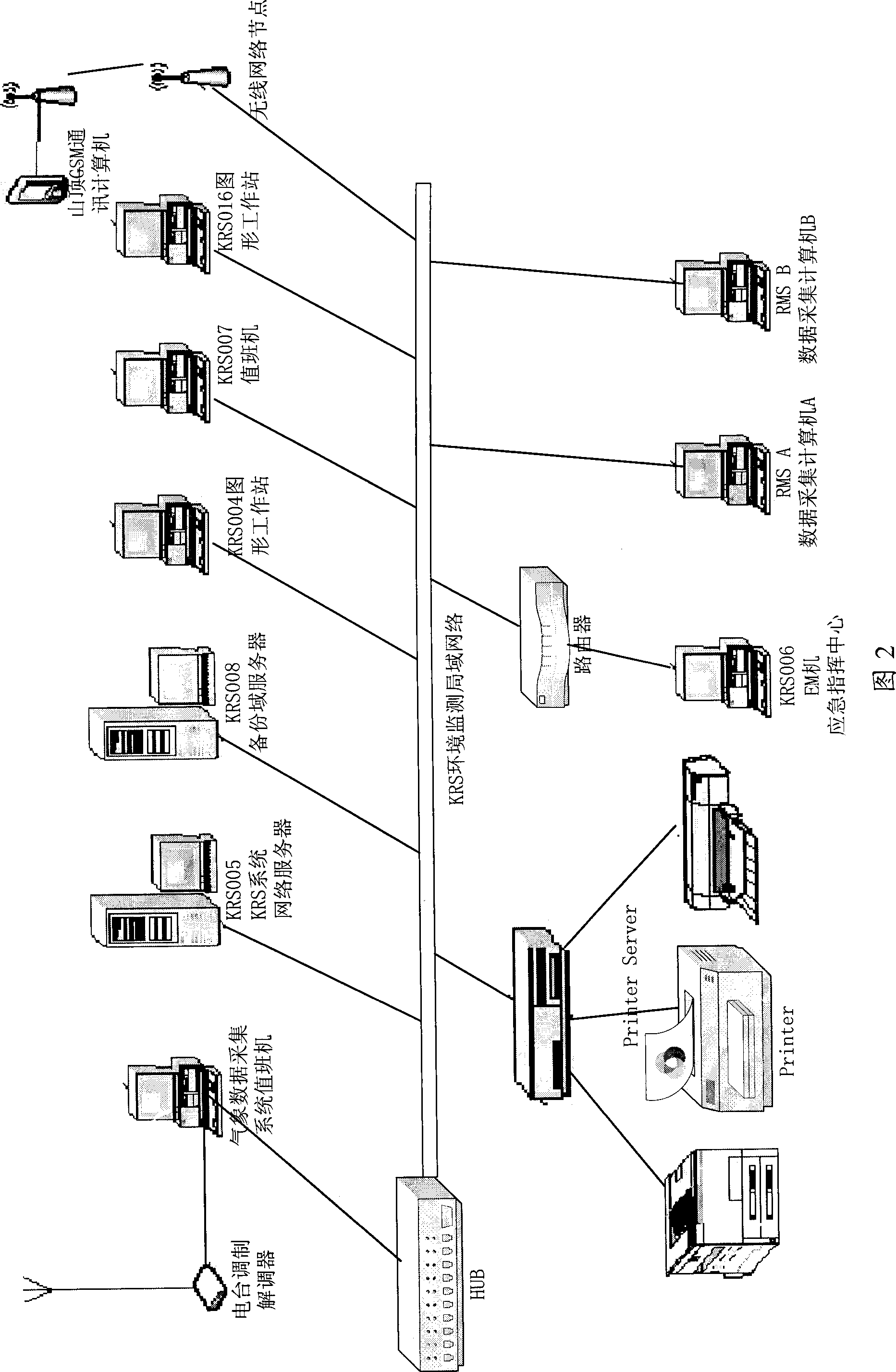
[0027] The emergency environmental radiation monitoring system of the present invention includes an environmental monitoring vehicle and a computer network system for emergency environmental radiation monitoring at a central station, and is used for environmental radiation survey during normal operation of nuclear power plants and real-time monitoring of environmental radiation in an emergency emergency state.

[0028] 1. Environmental monitoring vehicle

[0029] The environmental monitoring vehicle includes a carrying device, environmental monitoring equipment, vehicle power supply equipment, vehi...


PUM


Abstract

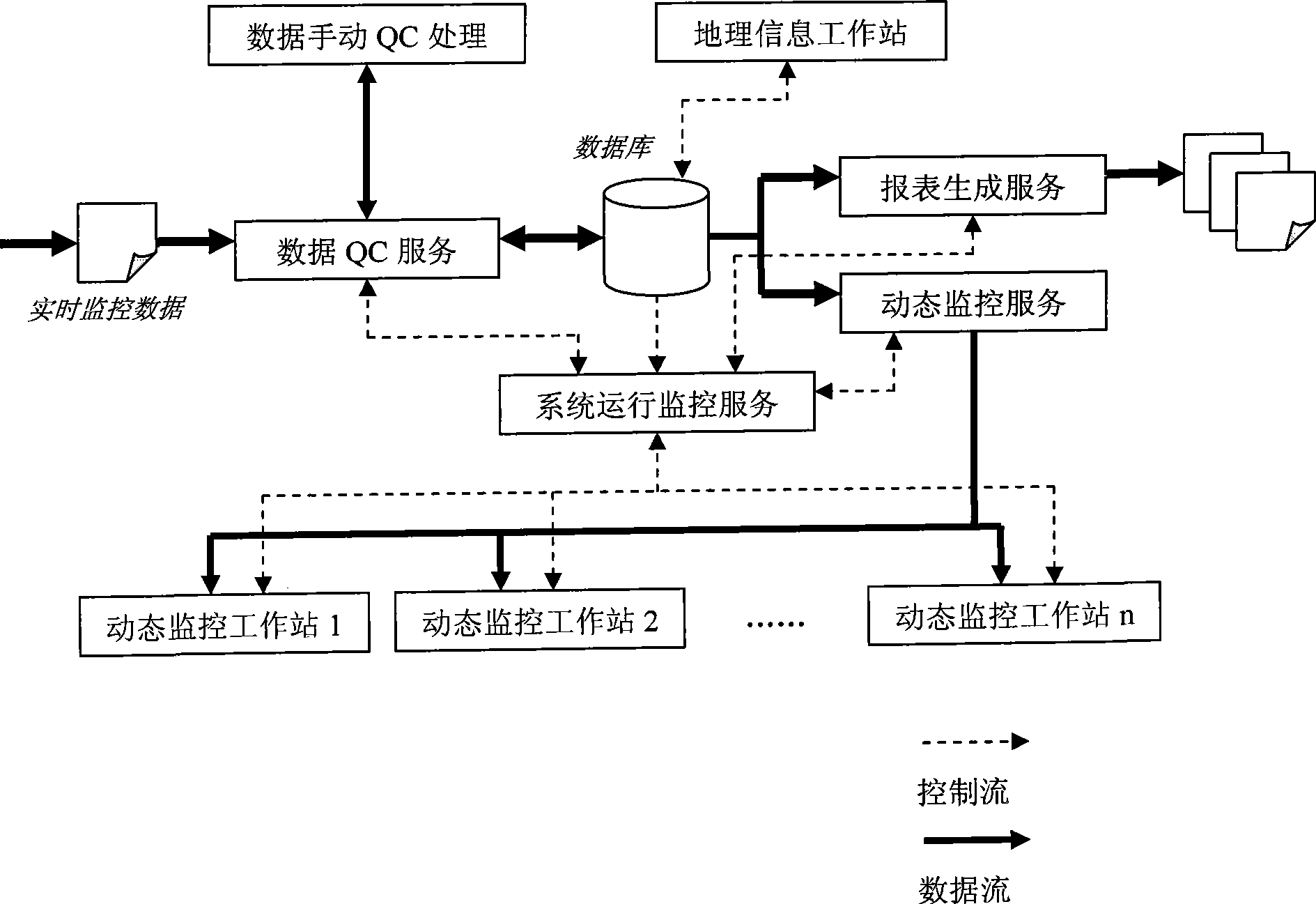
The embodiment of the invention discloses an emergency environment radiation monitoring system, comprising a mobile environment monitor and a center station emergency environment radiation monitor computer network system. The mobile environment monitor is arranged with an automobile gamma radiation automatic monitor, a globe positioning system GPS, two wireless communication devices which can be switched and a safe and reliable automobile power supplier, to confirm the operation stability and the reliability of real-time monitor and transmission of the system. The center station emergency environment radiation monitor computer network system adopts a digit electronic map technique adopting a geographic information GIS as a software platform, to real-timely display the gamma radiation monitor data and the GPS positioning information of the monitor on the electronic graphic interface of each network monitor station, thereby in-timely and accurately finding wind direction radioactive contamination region for nuclear power station accidents and providing reliable monitor information for emergency commanders, based on the decision of operational intervention level.

Description

technical field [0001] The invention belongs to an environmental radiation monitoring system, in particular to an emergency environmental radiation monitoring system. Background technique [0002] The old emergency environmental monitoring vehicle is equipped with G-M type gamma radiation detector, NaI gamma spectrometer, air sampling pump, portable generator and power supply. During the use, the inventor found that due to design defects, the old system has mainly There are problems in the following aspects: the generator is slow to start by manpower, and the noise is loud, the system equipment is unstable, and failures occur frequently, and the system availability is low. In particular, the monitoring vehicle does not have the functions of automatic positioning monitoring and real-time data transmission. It can only rely on manual positioning monitoring and manual reporting of monitoring data, and the work efficiency is low. The single voice communication method makes it i...

Claims


Application Information

Patent Timeline
Patent Type & Authority Applications(China)
IPC IPC(8): G01T1/00H04L12/28
Inventor 姜丽丽陈跃梅翔杰
Owner CHINA GENERAL NUCLEAR POWER CORP
Learn More