Waste heat recovery apparatus
A control device, technology for superheat, applied in engine components, machines/engines, internal combustion piston engines, etc.
- Summary
- Abstract
- Description
- Claims
- Application Information
AI Technical Summary
Problems solved by technology
Method used
Image
Examples
no. 1 approach
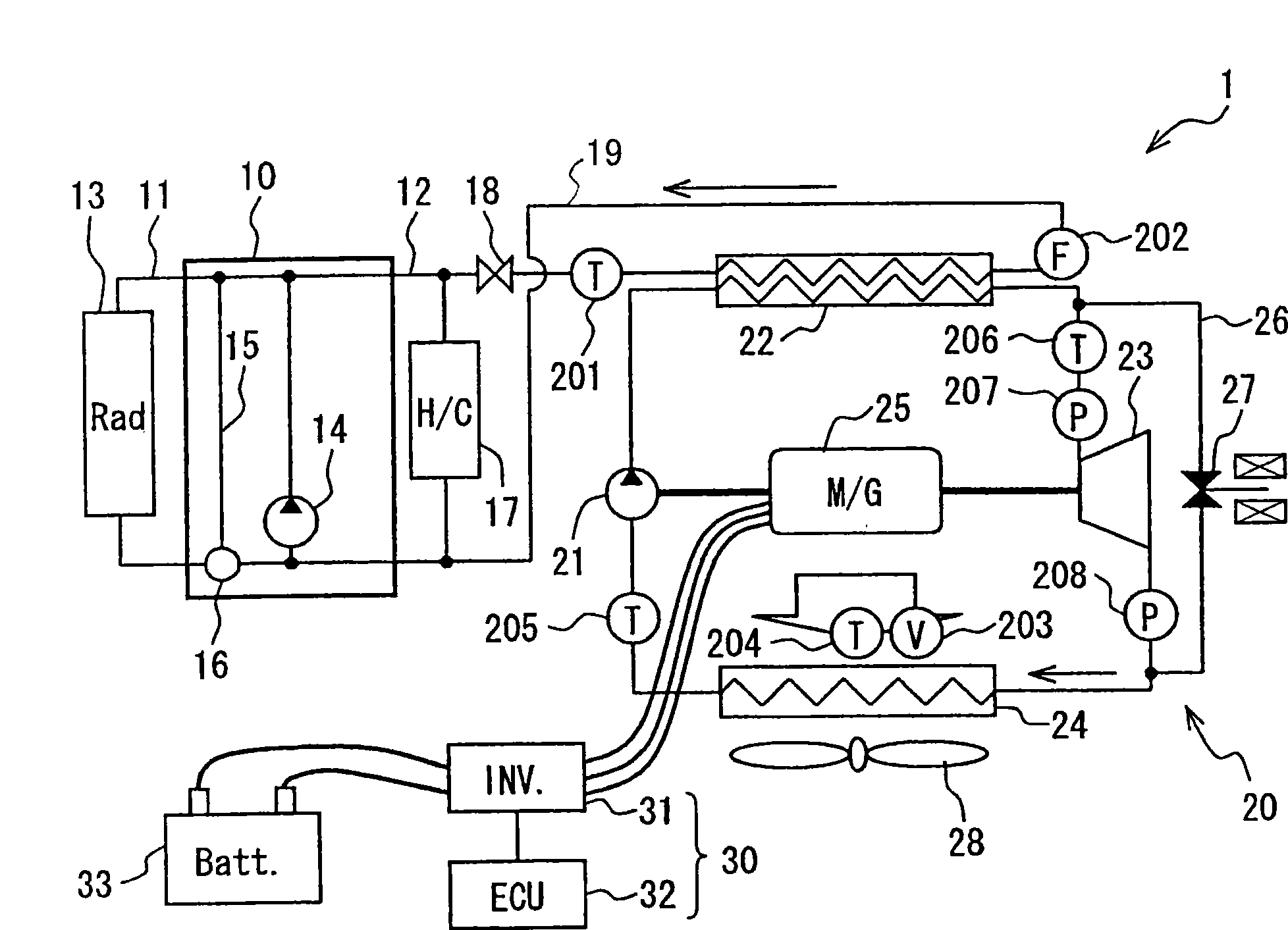
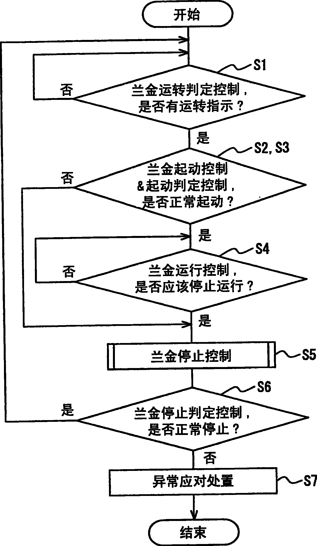
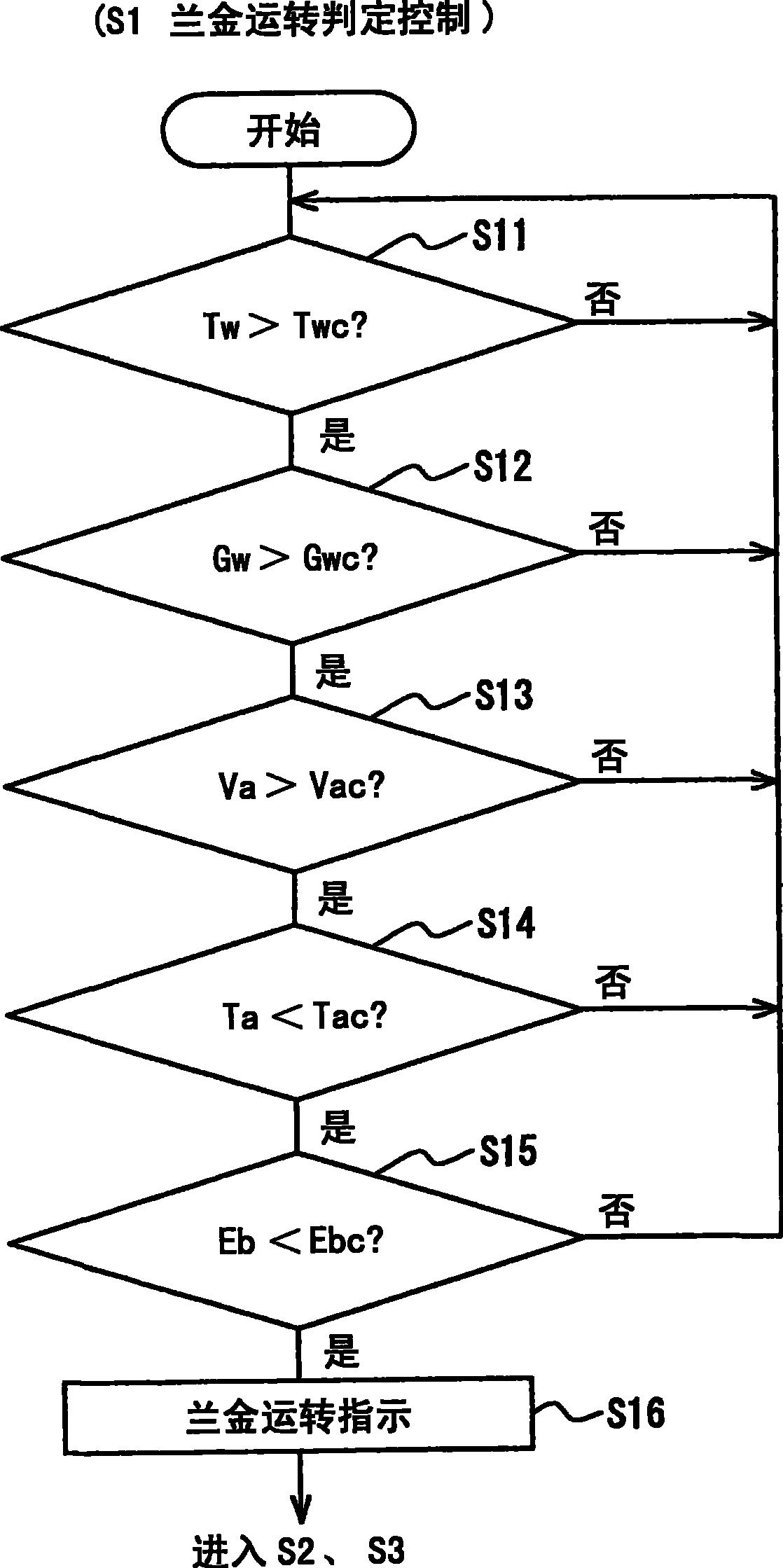
[0045] Hereinafter, regarding the first embodiment of the present invention, refer to Figure 1 to Figure 11 Be explained.
[0046] figure 1 It is a schematic diagram showing the whole system of the waste heat utilization device 1 having the Rankine cycle 20 . Such as figure 1 As shown, the waste heat utilization device 1 of this embodiment is applied to, for example, a vehicle that uses the engine 10 as a drive source.
[0047] The engine 10 is a water-cooled internal combustion engine. The engine is provided with a cooler circuit 11 that cools the engine 10 by circulation of engine cooling water, and a heater circuit 12 that heats conditioned air using cooling water (warm water) as a heat source.
[0048] A cooler 13 is arranged in the cooler circuit 11 . The cooler 13 cools the cooling water circulated by the warm water pump 14 by exchanging heat with the outside air. The warm water pump 14 may be an electric pump or a mechanical pump. A heater 22 of a Rankine cycl...
no. 2 approach
[0125] Next, regarding the second embodiment of the present invention, refer to Figure 12 , Figure 13 Be explained. In addition, in this embodiment, the steps common to the first embodiment are denoted by the same symbols as in the first embodiment, and the following description will focus on the parts different from the first embodiment.
[0126] Figure 12 It is a flowchart explaining the detail of Rankine operation control (S4) of this embodiment. In this embodiment, the highest and lowest rotational speed setting step (S411) of the Rankine operation control (S4) is different from the above-mentioned first embodiment, and other device configurations and controls are the same. Therefore, the maximum and minimum rotational speed setting step (S411) will be described in detail, and other descriptions will be omitted.
[0127] Such as Figure 12 As shown, in step S411, the increase or decrease of the maximum rotational speed Nmax_s of the expander 23 is determined accord...
no. 3 approach
[0143] Hereinafter, for the third embodiment of the present invention, refer to Figure 17 -20C for explanation.
[0144] Figure 17 It is a schematic diagram showing the whole system of the waste heat utilization device 1 having the Rankine cycle 20 according to the present embodiment. Figure 18 It is a flowchart showing the control (Rankine start control S2a) at the start of the Rankine cycle 20, which is the characteristic part of this embodiment, Figure 19 It is a time chart showing the pressure difference of the expander and the rotational speed of the pump expander from the start of the Rankine cycle 20 to normal control, Figure 20A -20C is a schematic diagram showing the refrigerant flow rate at each part when the Rankine cycle 20 is started.
[0145] In this embodiment, the pump 21 is connected to the generator 25 and the expander 23 through the same drive shaft. Hereinafter, the same reference numerals are assigned to the same parts as those of the first embodi...
PUM
 Abstract
Description
Claims
Application Information
 - Generate Ideas
- Intellectual Property
- Life Sciences
- Materials
- Tech Scout
- Unparalleled Data Quality
- Higher Quality Content
- 60% Fewer Hallucinations
Browse by: Latest US Patents, China's latest patents, Technical Efficacy Thesaurus, Application Domain, Technology Topic, Popular Technical Reports.
© 2025 PatSnap. All rights reserved.Legal|Privacy policy|Modern Slavery Act Transparency Statement|Sitemap|About US| Contact US: help@patsnap.com


