
Wireless communication system

A wireless communication system and wireless transmission technology, applied in wireless communication, image communication, cathode ray tube indicator, etc., can solve the problems of time-consuming cable connection, messy appearance, time-consuming EDID information, etc., and achieve a neat appearance. Effect

Inactive Publication Date: 2009-03-11
PANASONIC CORP
View PDF1 Cites 15 Cited by
  • Summary
  • Abstract
  • Description
  • Claims
  • Application Information

AI Technical Summary

Problems solved by technology

[0005] However, in the transmission method and system of the above-mentioned patent document 1, in order to send and receive EDID and set the physical address, wires are used, but due to the wiring, not only the appearance It is messy, and each communication device can only communicate with one communication device. When communicating with other communication devices, there is a problem that it takes man-hours to replace the connection of each cable
[0006] In addition, since DDC (Display Data Channel) is used to read EDID information between communication devices, there is a problem that it takes time to read EDID information.

Method used


Image

  • Wireless communication system
  • Wireless communication system
  • Wireless communication system

Examples


no. 2 Embodiment approach

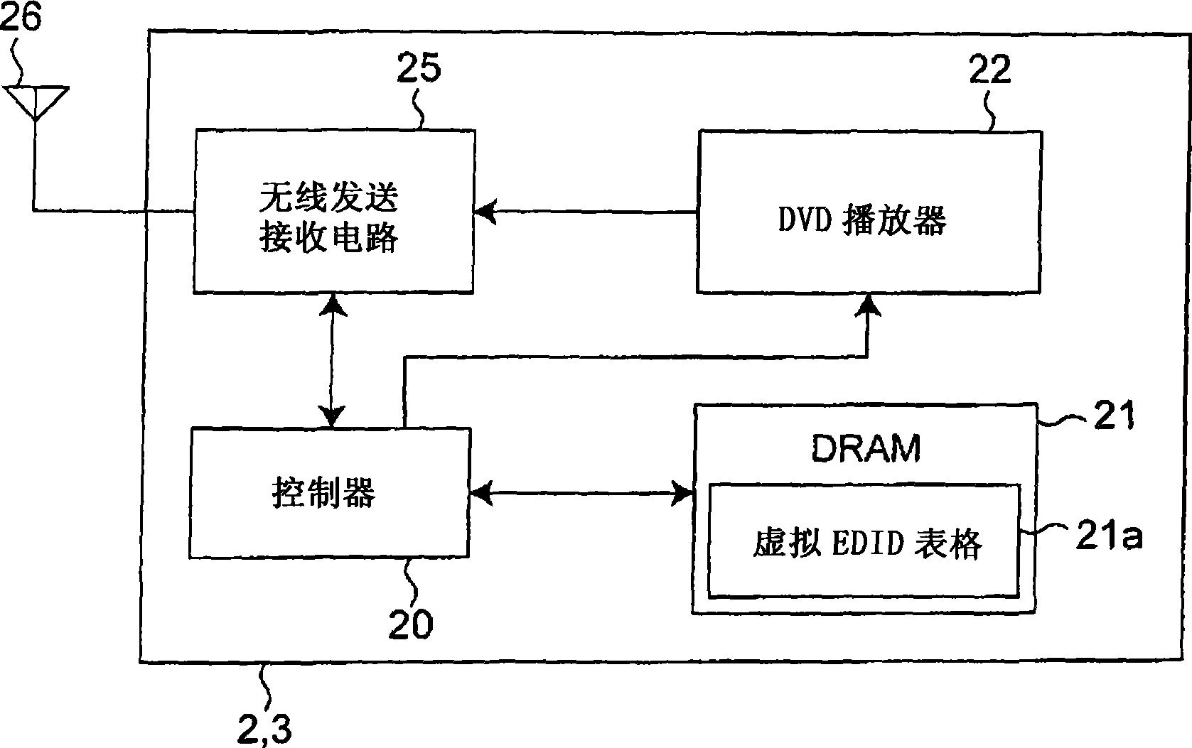
[0073] 12 is a block diagram showing the configuration of a sink device 1A and a sink device adapter device 35 in a wireless communication system according to a second embodiment of the present invention. FIG. 13 is a block diagram showing the configurations of the source device 2A and the source device adapter device 45 of the wireless communication system according to the present embodiment. In FIGS. 12 and 13 , the wireless communication system according to this embodiment is configured to include a sink device 1A, a source device 2A, an adapter device 35 for a sink device, and an adapter device 45 for a source device. The sink device 1A shown in FIG. 12 is similar to the first embodiment shown in FIG. 2 in that it has a controller 10A and a wired transmission and reception circuit 33 instead of the controller 10, DRAM 12, wireless transmission and reception circuit 15, and antenna 16 in FIG. The sink device 1 related to the wireless communication system is different. In a...


PUM


Abstract

In a wireless communication system including source devices (2, 3) for transmitting video signals by wireless, a sink device (1) for receiving the transmitted video signal and displaying the received video signal on a display device (13), the sink device (1) reads out EDID information from a ROM (11) and transmits wireless-data signal including it by wireless to source devices (2,3). The source devices (2, 3) receive by wireless the wireless-data signal including the EDID information transmitted by wireless and transmit video signals to the sink device (1) by wireless on a basis of the EDID information.

Description

technical field [0001] The present invention relates to a sink device, a source device, an adapter device for the sink device, An adapter device for a source device, a wireless communication system and a control method thereof. Background technique [0002] Patent Document 1 discloses a transmission system in which a physical address is set by transmitting and receiving EDID (Extended Display Identification Data) via a cable in HDMI (High-Definition Multimedia Interface). The transmission system of Patent Document 1 includes a receiver, a transmitter, and a serial link, and transmits encoded data (such as video, audio, and additional auxiliary data) from the transmitter to the receiver [0003] Patent Document 1: Special Publication No. 2005-514873. [0004] Non-Patent Document 1: High—Definition Multimedia Interface Specification, Version 1.1, HDMI Licensing, LLC, California in U.S.A., May 20, 2004. [0005] However, in the transmission method and system of the above-men...

Claims


Application Information

Patent Timeline
Patent Type & Authority Applications(China)
IPC IPC(8): H04L12/28H04N21/436
CPCG09G5/006G09G2370/042G06F3/14H04W28/18G09G2370/16G09G2360/02G09G2340/0407H04N21/43637G09G2350/00
Inventor 船引诚龙田明浩大植裕司
Owner PANASONIC CORP
Learn More