
Virtual MIMO matching method for uplink multiuser equipment

A multi-input, multi-user technology, applied in diversity/multi-antenna systems, space transmit diversity, error prevention/detection through diversity reception, etc., to achieve the effect of reducing dimensionality restrictions, increasing uplink capacity and UE throughput

Inactive Publication Date: 2009-03-11
ZTE CORP
View PDF0 Cites 27 Cited by
  • Summary
  • Abstract
  • Description
  • Claims
  • Application Information

AI Technical Summary

Problems solved by technology

[0004] The technical problem to be solved by the present invention is to provide an uplink multi-UE virtual MIMO pairing method to solve the problem that UEs that only use one antenna can also apply MIMO technology when transmitting, thereby effectively utilizing existing channel resources

Method used


Image

  • Virtual MIMO matching method for uplink multiuser equipment
  • Virtual MIMO matching method for uplink multiuser equipment
  • Virtual MIMO matching method for uplink multiuser equipment

Examples


Embodiment Construction

[0028] In the embodiment of the present invention, the NodeB needs to schedule and allocate two UEs in a pairing mode, and the two UEs in the virtual MIMO need to use orthogonal pilots to perform channel estimation.

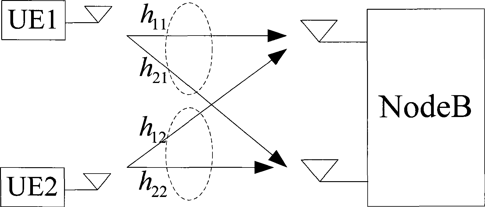
[0029] Each UE only uses 1 transmit antenna when sending data, and the base station (Node B) has 2 receive antennas (the base station has multiple antennas, but the present invention is for the situation that Node B has 2 receive antennas), then UE1 and The channel matrix between NodeBs is H 1 =[h 11 h 21 ] T , the channel matrix between UE2 and NodeB is H 2 =[h 12 h 22 ] T (where T refers to the transpose of the matrix), such as figure 1 shown.

[0030] Then the premise that there is no interference between the two UEs is: the inner product between the column vectors of the two channel matrices is 0, that is: h 11 ...


PUM


Abstract

The invention discloses a pairing method for virtual multi-input multi-output of up multi-user equipment UE, which is applied to condition that one sending antenna is used when each UE sends data and two sending antennae are used when a base station Node B receives data. The Node B pairs a plurality of UEs according to a codebook corresponding to each UE channel matrix so as to cause the inner product between column vectors of the codebooks corresponding to two paired UEs to be zero. An up virtual MIMO provided by the invention allows two UEs having sending antennae to transmit the data on the same resources (including the time, the frequency range resources, the spreading codes and the like). The pairing method can lower the dimension limit of an orthogonal system, and can increase the up capacity and the UE throughput.

Description

technical field [0001] The present invention relates to a Multiple Input and Multiple Output (MIMO, Multiple Input and Multiple Output) wireless mobile communication system, in particular to a virtual MIMO pairing method applied to uplink multi-User Equipment (UE, User Equipment). Background technique [0002] MIMO technology is aimed at multi-path wireless channels. It refers to the use of multiple transmitting antennas and receiving antennas at the transmitting end and receiving end respectively, so as to increase the data rate, reduce the bit error rate, and improve the quality of wireless signal transmission. The MIMO wireless mobile communication system has become a technology that has attracted much attention in the research of LTE (Long Term Evolution) because it can effectively improve the channel capacity. [0003] Using precoding technology to multiplex between multiple data streams and antennas can make more effective use of existing channel resources. The basic i...

Claims


Application Information

Patent Timeline
Patent Type & Authority Applications(China)
IPC IPC(8): H04B7/04H04L1/06
Inventor 郭阳
Owner ZTE CORP
Learn More