Multi-beam infrared railings sounder having intrusion directional recognition and sounding method
A technology of direction identification and infrared emitter, which is applied in the field of alarm manufacturing, can solve the problems of restricting the popularization of infrared fences, failing to achieve monitoring and alarm, and not having direction identification, etc., and achieves novel structural design, low false alarm rate, and convenient Promoted app performance
- Summary
- Abstract
- Description
- Claims
- Application Information
AI Technical Summary
Problems solved by technology
Method used
Image
Examples
Embodiment 1
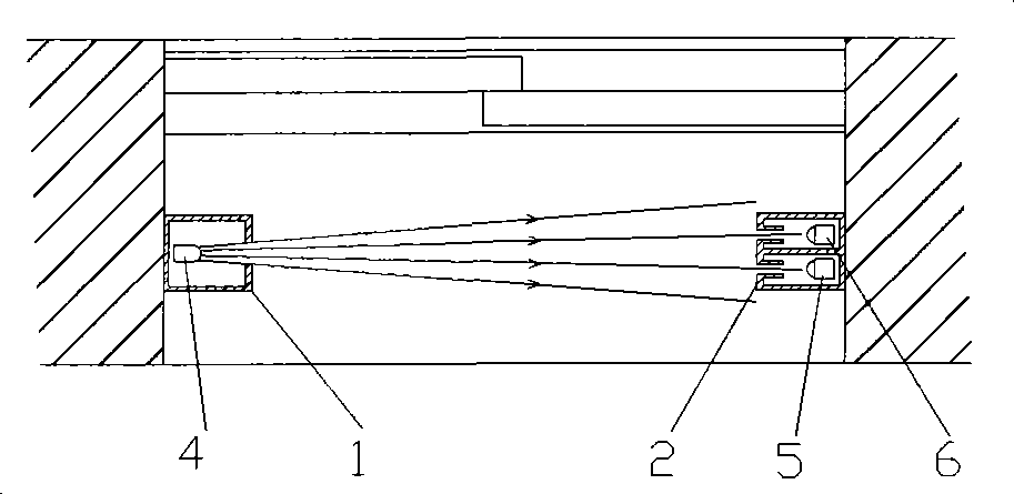
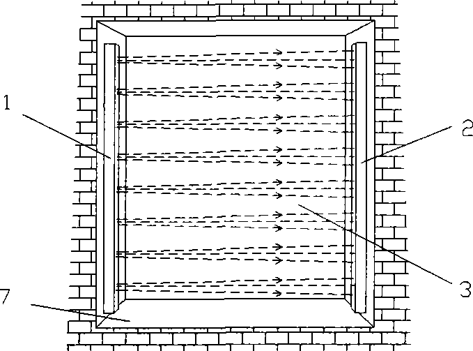
[0016] Embodiment 1: with reference to attached figure 1 and 2 . A multi-beam infrared fence detector with intrusion direction recognition, it includes an infrared transmitter 1 and an infrared receiver 2, and a multi-beam infrared grating is formed between the infrared transmitter 1 and the infrared receiver 2 to form a planar defense net 3, said Each beam of infrared emitters contains at least one infrared transmitter 4 and two infrared receivers (infrared receiver A5 and infrared receiver B6), and the arrangement of the two infrared receivers in each infrared beam is X-axis It is still the Y axis, which is arranged one after the other in the direction perpendicular to the X axis and the Y axis. One of the two infrared receiving heads is an infrared trigger head, and the other is an infrared non-trigger head. Controlled by the infrared trigger head or controlled by the infrared non-trigger head, any one of the two infrared receivers can be used as either an infrared trigge...
Embodiment 2
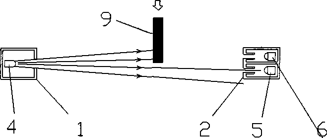
[0018] Embodiment 2: On the basis of Embodiment 1, refer to accompanying drawings 3-5. An infrared protective net composed of a multi-beam infrared fence detector with intrusion direction recognition, it includes a rectangular frame 7 or a non-rectangular frame, and the rectangular frame or non-rectangular frame is on the side of the frame column relative to the frame column from top to bottom or from the left And the right interval is distributed with many beams of infrared transmitters 1, and the other side frame column of the opposite frame column is distributed with multiple beams of infrared receivers 2 at intervals from top to bottom or from left to right and the multiple beams of infrared receivers 2 are opposite to it The infrared emitters 1 constitute an infrared fence detector network 3, and the multi-beam infrared emitters 1 and the multi-beam infrared receivers 2 on the non-rectangular frame are opposite one by one.
[0019] With reference to accompanying drawing F...
Embodiment 3
[0022] Embodiment 3: On the basis of Embodiments 1 and 2, refer to accompanying drawings 3-5. A detection method for an infrared protective net composed of a multi-beam infrared fence detector with intrusion direction recognition, a multi-beam infrared transmitter distributed in a rectangular frame or a non-rectangular frame and a corresponding multi-beam infrared receiver constitute an infrared fence detection The two infrared receiving heads in each bundle of infrared receivers, one in front and one in the back, the front infrared receiving head is the triggering infrared receiving head or the rear infrared receiving head is the non-triggering infrared receiving head. When entering from the direction of the head, the infrared trigger head triggers the infrared fence detector net to alarm, and when people or objects enter from the direction of the non-triggering infrared receiving head, the infrared trigger head does not trigger the infrared fence detector net to alarm.
PUM
 Abstract
Description
Claims
Application Information
 - R&D Engineer
- R&D Manager
- IP Professional
- Industry Leading Data Capabilities
- Powerful AI technology
- Patent DNA Extraction
Browse by: Latest US Patents, China's latest patents, Technical Efficacy Thesaurus, Application Domain, Technology Topic, Popular Technical Reports.
© 2024 PatSnap. All rights reserved.Legal|Privacy policy|Modern Slavery Act Transparency Statement|Sitemap|About US| Contact US: help@patsnap.com


