Technique for producing oil products by fischer-tropsch synthesis

A technology of Fischer-Tropsch synthesis and process method, applied in the petroleum industry, recovery of liquid hydrocarbon mixtures, etc., can solve the problems of increasing the design diameter of the reactor, reducing the partial pressure of the effective gas reaction, and increasing the cycle power consumption, so as to save investment Effects of cost and operating energy consumption, improvement of effective gas composition, and improvement of space-time yield

Active Publication Date: 2012-10-17
YANKUANG ENERGY R&D CO LTD
View PDF1 Cites 3 Cited by
  • Summary
  • Abstract
  • Description
  • Claims
  • Application Information

AI Technical Summary

Problems solved by technology

[0009] (1) This process is only for the low-temperature Fischer-Tropsch synthesis process, and the reactor type suitable for different Fischer-Tropsch synthesis processes cannot be configured according to product requirements
[0010] (2) The corresponding relationship between the primary and secondary synthesis reactors is not clear in the disclosed scheme of the process. According to its embodiment, the implicit scheme is that each primary synthesis reactor corresponds to a secondary synthesis reactor. The inlet gas volume of the first-stage synthesis reactor is much lower than that of the first-stage synthesis reactor, so the size of the second-stage synthesis reactor is also much lower than that of the first-stage synthesis reactor, and the processing capacity of the first-stage and second-stage single reactors is quite different
[0011] (3) In the disclosed scheme of the process, the primary tail gas is recycled back to the primary reactor and enters the secondary reactor without any treatment, and the secondary tail gas is recycled back to the secondary reactor without any treatment. Other components in the gas points (mainly CO 2 ) In addition to reducing the reaction partial pressure of the effective gas and increasing the gas flow rate, the design diameter of the reactor will be increased, and the cycle power consumption will also increase

Method used


Image

  • Technique for producing oil products by fischer-tropsch synthesis
  • Technique for producing oil products by fischer-tropsch synthesis
  • Technique for producing oil products by fischer-tropsch synthesis

Examples


Embodiment 1

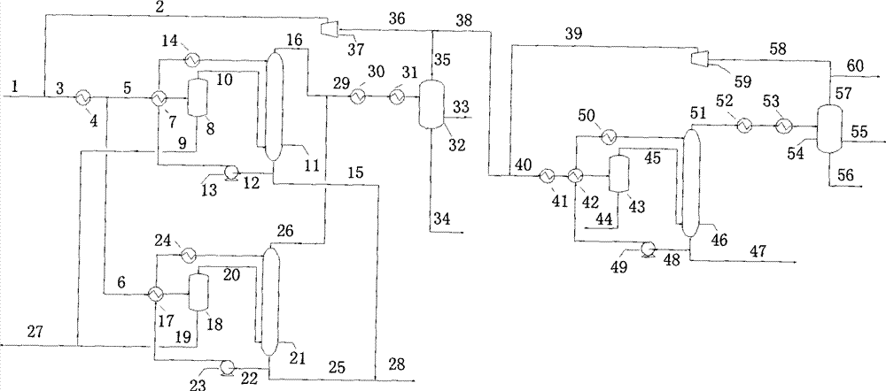
[0036] The main feature of this embodiment is that two-stage Fischer-Tropsch synthesis is adopted, wherein two first-stage Fischer-Tropsch synthesis reactors are connected in parallel, and the second-stage Fischer-Tropsch synthesis reactor is single. Such as figure 1 As shown, the first-stage Fischer-Tropsch synthesis reactor is two parallel reactors, and the second-stage Fischer-Tropsch synthesis reactor is a single one. The primary and secondary Fischer-Tropsch synthesis are both low-temperature Fischer-Tropsch synthesis, using a slurry bed reactor.

[0037] The temperature of fresh syngas 1 is 40°C, the pressure is 2.9MPaG, and the flow rate is 780000Nm 3 / h, the molar composition is H 2 : 0.617, CO: 0.374, CO 2 : 0.004, Ar: 0.001, CH 4 :0.001,N 2 : 0.004. The fresh synthesis gas 1 is mixed with the exhaust gas 2 of the first-stage synthesis cycle. After the mixed gas stream 3 is preheated by the heat exchanger 4, it is divided into two streams 5 and 6 on average, and...

Embodiment 2

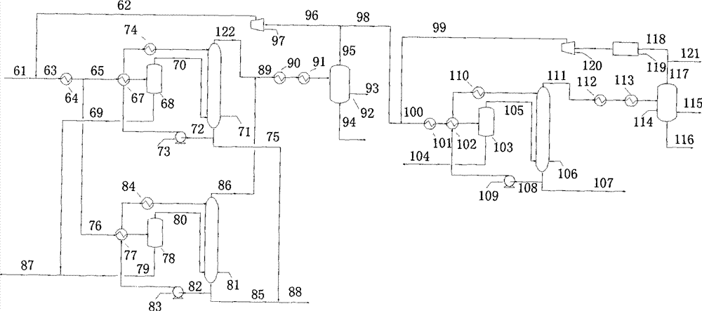
[0047] The difference between the process of Example 2 and that of Example 1 is that the circulating tail gas of the secondary synthesis reactor is decarburized and then recycled back to the inlet of the secondary synthesis reactor, and the rest of the process configurations are the same. Such as figure 2 As shown, the first-stage Fischer-Tropsch synthesis reactor is two parallel reactors, and the second-stage Fischer-Tropsch synthesis reactor is single, but the tail gas of the second-stage Fischer-Tropsch synthesis is recycled to the second-stage synthesis reactor after decarburization. The primary and secondary Fischer-Tropsch synthesis are both low-temperature Fischer-Tropsch synthesis, using a slurry bed reactor. The secondary gas circulation ratio remains the same as in Example 1, and the reactor size is also consistent.

[0048] The pressure, flow rate and gas composition of the fresh syngas are the same as in Example 1.

[0049] Fresh synthesis gas 61 is mixed with p...

Embodiment 3

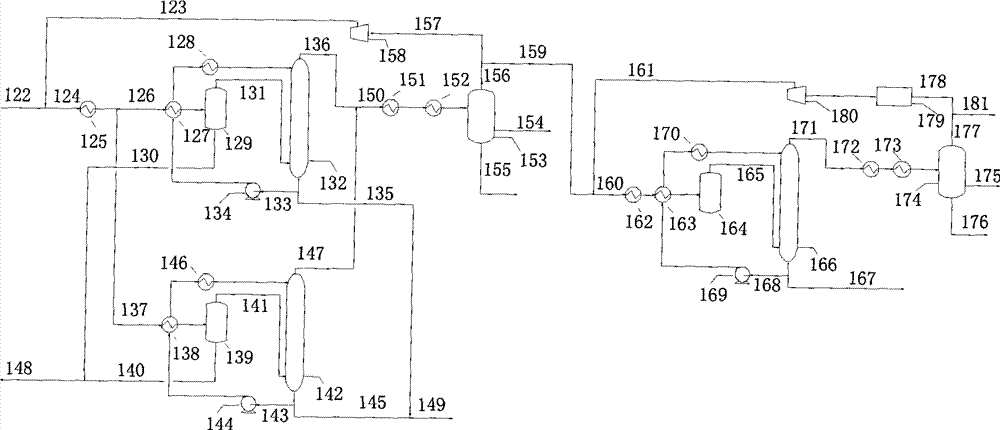
[0059] Embodiment 3 has also adopted the process of secondary tail gas decarburization, and the difference from Example 2 is that the secondary Fischer-Tropsch synthesis adopts a high-temperature Fischer-Tropsch synthesis process, and the secondary Fischer-Tropsch synthesis reactor adopts a fluidized bed reactor. The scheme of high-level synthetic products is also different from the previous two cases. Such as image 3 As shown, the first-stage Fischer-Tropsch synthesis reactor is two parallel reactors, the second-stage Fischer-Tropsch synthesis reactor is single, and the tail gas of the second-stage Fischer-Tropsch synthesis is decarburized and then recycled back to the second-stage synthesis reactor. For low-temperature Fischer-Tropsch synthesis, a slurry bed reactor is used; however, the second-stage Fischer-Tropsch synthesis is a high-temperature Fischer-Tropsch synthesis process, and the reactor is a fluidized bed reactor, but the size of the second-stage reactor is the s...


PUM


Abstract

The invention relates to a technological method for preparing oil products by the Fischer-Tropsch synthesis. In the technological method, a FT synthesis process comprises a first-stage FT synthesis process and a second-stage FT synthesis process; in particular, the technological method comprises the following steps: (1) synthesis gases are subjected to FT synthesis reaction in a first-stage synthesis reactor; (2) a part of tail gases from the first-stage synthesis reactor are circularly returned to an entrance of the first-stage synthesis reactor, and another part of the tail gases enter a second-stage synthesis reactor for the further FT synthesis reaction; (3) a part of tail gases from the second-stage synthesis reactor are circularly returned to an entrance of the second-stage synthesis reactor, and another part of the tail gases are used for reclaiming low-carbon hydrocarbons and hydrogen gases and then are used as fuel gases; and (4) by utilizing the recovered hydrogen gases, thehydrocarbon products in the first-stage synthesis reactor and the second-stage synthesis reactor and the hydrocarbon products which are obtained by separating and recovering the tail gases are subjected to hydrogenation and purification and then are fractionated to generate various oil products. Compared with prior art, the technological method has the characteristics of economy, flexibility, lowcost and the like.

Description

technical field [0001] The invention relates to an oil production method, in particular to a process for producing liquid oil by Fischer-Tropsch synthesis using synthetic gas as a raw material. Background technique [0002] Synthesis gas is produced from coal or natural gas. Synthesis gas is synthesized by Fischer-Tropsch synthesis into hydrocarbons, and hydrocarbons are processed into liquid oil in one step. The indirect coal liquefaction process is an important strategy for clean energy utilization and energy substitution in the 21st century. One of the directions of technological development. [0003] According to the main results of existing literature review, the Fischer-Tropsch synthesis process is briefly described as follows: [0004] Syngas as H 2 With the mixed gas mainly composed of CO, the Fischer-Tropsch synthesis reaction occurs under the action of the Fischer-Tropsch synthesis catalyst to generate liquid hydrocarbon products. The type and quantity of produc...

Claims


Application Information

Patent Timeline
Patent Type & Authority Patents(China)
IPC IPC(8): C10G5/00
Inventor 孙启文朱继承
Owner YANKUANG ENERGY R&D CO LTD
Why Eureka
Try Eureka