
Rubber track and chain wheel suitable for rubber track and core iron for rubber track

A technology of rubber track and sprocket, which is applied in the field of rubber track and sprocket, so-called rubber track, which can solve the problems of insufficient consideration of the situation from the roller to the driving protrusion, the degradation of the appearance quality of the rubber track, and the decrease of the guiding function. Achieve surface pressure reduction, achieve durability, and reduce surface pressure

Active Publication Date: 2009-03-11
BRIDGESTONE CORP
View PDF2 Cites 25 Cited by
  • Summary
  • Abstract
  • Description
  • Claims
  • Application Information

AI Technical Summary

Problems solved by technology

Therefore, there is a problem that the rubber crawler easily damages or damages the surroundings of the driving protrusions.
[0012] In addition, the conventional rubber track described in Patent Document 2 does not fully consider the situation where the roller goes to the driving protrusion.
That is, in the rubber crawler described in Patent Document 2, the driving projections are formed by covering the corners of the core bone with a thick rubber material in the circumferential direction of the rubber crawler with which the sprocket teeth are engaged. When the roller is on the driving protrusion, the rubber material covering its corner is prone to great deformation and falls off; when the rubber material falls off, the guiding function of the driving protrusion to prevent the roller from falling out will be reduced, and the rubber track will also be damaged. The appearance quality of , so there is still room for improvement on this point

Method used


Image

  • Rubber track and chain wheel suitable for rubber track and core iron for rubber track
  • Rubber track and chain wheel suitable for rubber track and core iron for rubber track
  • Rubber track and chain wheel suitable for rubber track and core iron for rubber track

Examples


Embodiment Construction

[0048] Hereinafter, an embodiment of the present invention will be described in detail with reference to the drawings. Embodiments of the first invention and the second invention described above will be described in order.

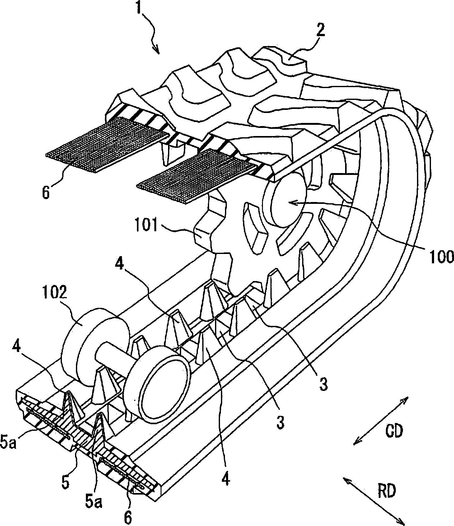
[0049] figure 1 It is a perspective view which shows part of the rubber crawler in embodiment of 1st invention. Should figure 1 The sprockets that transmit the driving force (rotational force) to the rubber track are also illustrated accordingly.

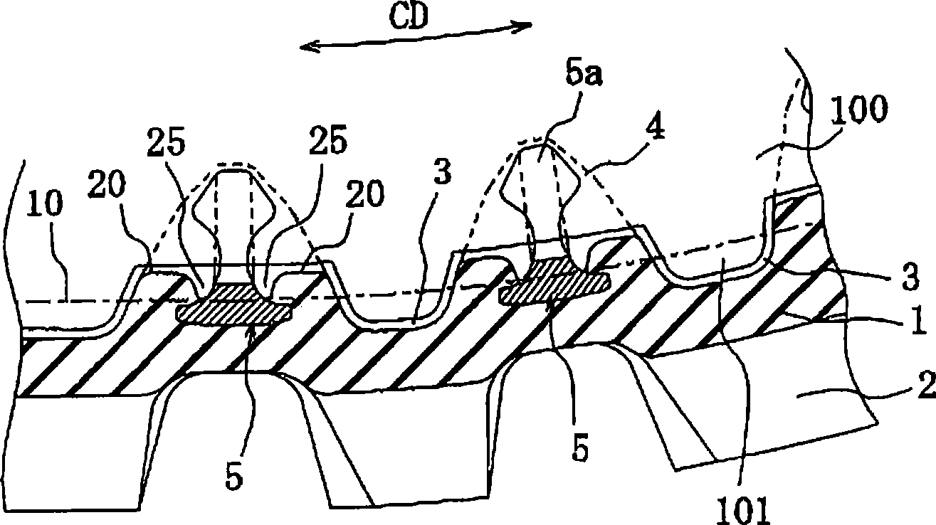
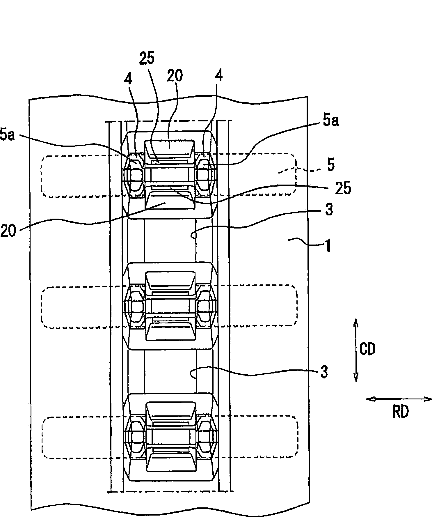
[0050] figure 1 The rubber crawler 1 is a so-called inner peripheral drive type rubber crawler, which has a tooth portion 2 acting on the road surface on its outer peripheral surface side, and a drive card for transmitting the driving force to the rubber crawler itself is formed on its inner peripheral surface side. Hebu. The driving engaging part includes: the following hard engaging members buried in the circumferential direction of the rubber crawler 1 at a constant pitch; and recesses 3 respectively arr...


PUM


Abstract

The invention provides a rubber track, a chain wheel suitable for the rubber track, and a core rod for the rubber track. The outer peripheral face of the rubber track (1) is provided with a projecting part (2), and the inner peripheral face is provided with a driving clamping part for transferring a driving force which is transferred through clamping of the chain wheel (100) and the driving clamping part, wherein the driving clamping part comprises hard clamping components (5) embedded in the circumferential direction of the rubber track by a certain pitch, and a concave part (3) arranged among the clamping components (5) to receive a tooth part of the chain wheel. According to the rubber track, the tooth part of the chain wheel is clamped with the concave part between the hard clamping components; therefore, compared with the prior condition that the tooth part is abutted with a driving protrusion projecting on the inner peripheral face, damage can be inhibited. Moreover, the shape of the concave part is properly changed to increase the area blocking with the tooth part, so as to reduce surface pressure.

Description

technical field [0001] The invention of the present application relates to a so-called rubber track. The present invention includes the first invention and the second invention. [0002] The first invention relates to a rubber crawler and a sprocket used in a vehicle running part, and more specifically, to a rubber crawler with improved durability and a sprocket suitable for the rubber crawler. [0003] In addition, the second invention relates to a rubber crawler and an arbor used for its driving protrusions, and particularly to a rubber crawler and an arbor for the rubber crawler that can suppress damage to the driving protrusions and suppress noise during running. Background technique [0004] In recent years, in consideration of road surface protection, noise suppression, and environmental protection, rubber crawlers have been widely used on the running parts of vehicles such as construction machinery and agricultural machinery. As such a rubber crawler, for example, a...

Claims


Application Information

Patent Timeline
Patent Type & Authority Applications(China)
IPC IPC(8): B62D55/24B62D55/253B62D55/12
Inventor 下薗靖夫
Owner BRIDGESTONE CORP
Learn More