Device for comminuting all types of parts

A technology for pulverizing equipment and components, applied in grain processing and other directions, can solve the problems of difficult input, reduction, and loud emission of materials to be pulverized

Inactive Publication Date: 2013-02-20
HERBOLD MEXHEIM GMBH
View PDF1 Cites 0 Cited by
  • Summary
  • Abstract
  • Description
  • Claims
  • Application Information

AI Technical Summary

Problems solved by technology

Therefore, feeding the material to be shredded into the rotor is a major challenge
Furthermore, when the material to be comminuted is conveyed in the region of the rotor in the known manner, it has been found that considerable acoustic emissions occur which must be reduced

Method used


Image

  • Device for comminuting all types of parts
  • Device for comminuting all types of parts
  • Device for comminuting all types of parts

Examples


Embodiment Construction

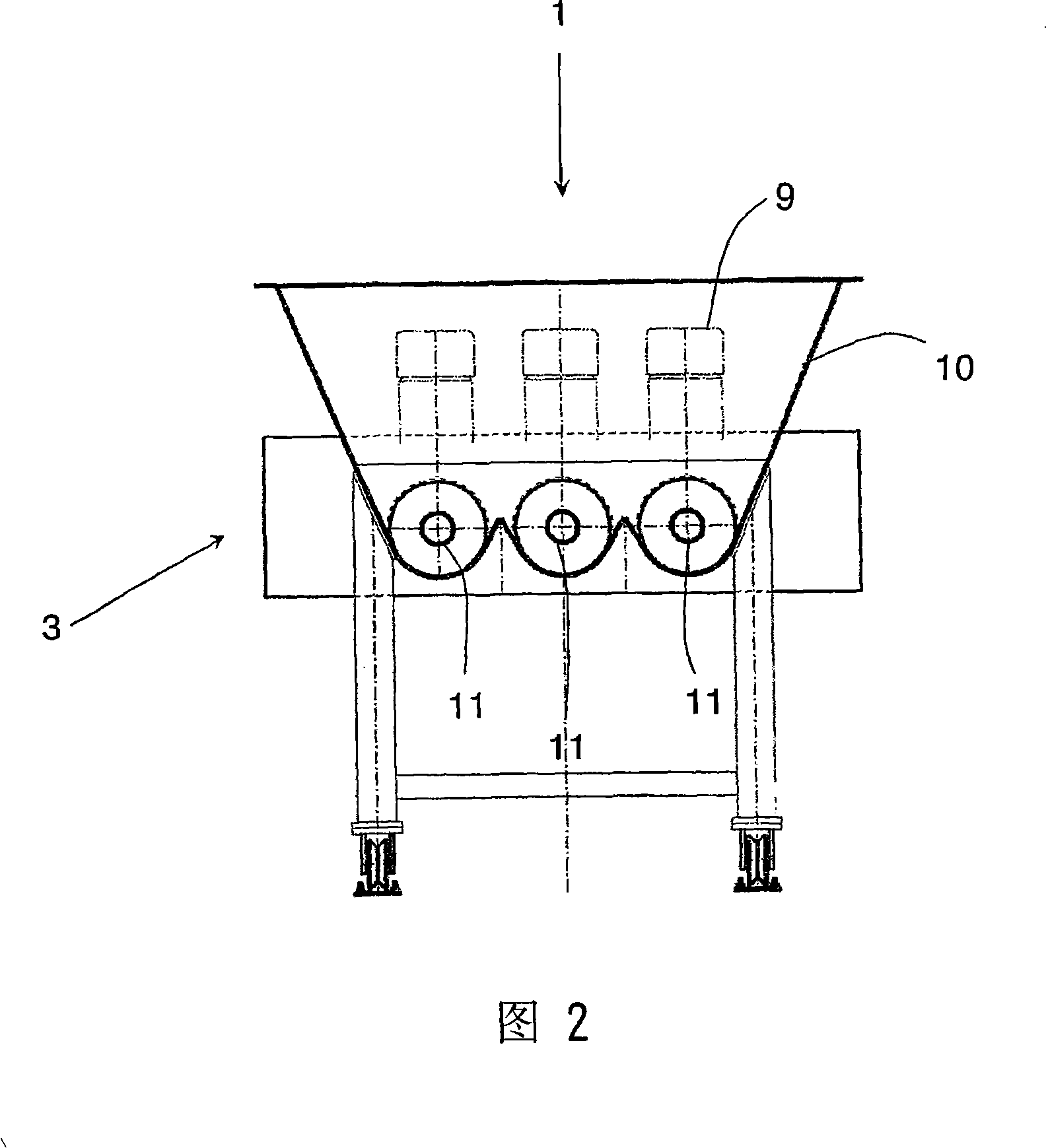
[0024] Figures 1 to 3 show an embodiment of a comminuting device for various types of components according to the present invention, wherein, in particular, the device is for comminuting plastic hollow bodies (not shown). Plastic bottles, such as PET bottles, are often shredded using such a device. The device comprises a feeding device 1 and a crushing device 2 . In the illustrated embodiment, the feeding device 1 comprises three conveying units 3 in total. The comminuting device 2 comprises a rotor 4 which is equipped with tools and rotates in a housing 5 . The housing 5 (sometimes also referred to as the stator) also houses the tool 6 .

[0025] 1 to 3 show that the delivery unit 3 is conveyed orthogonally to the axis of rotation 7 , which can be arranged at an angle in the range of 45° to 90° to the axis of rotation 7 in a manner according to the invention.

[0026] Furthermore, the drive 8 of the rotor and the drive 9 of the conveying unit 3 are shown in the figure. Th...


PUM


Abstract

Device for comminuting all types of parts, especially plastics, preferably hollow plastic bodies such as plastic bottles. The device comprises feed device (1), comminuting unit (2). The feed unit has a transport unit (3) and the comminuting unit has a rotor (4) rotating in a housing (5) and fitted with tools. The transport unit transports the parts at an angle of 45 to 90 deg to the rotor axis at least in the region directly in front of the rotor.

Description

technical field [0001] The present invention relates to a comminuting plant for various types of components, especially plastics, preferably plastic hollow bodies, such as plastic bottles, with a feeding device and a comminuting device, the feeding device comprising at least one conveying unit, the comminuting device Consists of a rotor that holds the tool and turns within a housing. Background technique [0002] It is well known that common models of equipment have been used for many years in many different embodiments. In this respect only German patent DE3813879 is cited as an example. In particular, known devices are shredders for waste thermoplastics. The material to be shredded is transported through the hopper and directly through the hopper from the conveying unit to the existing shredder, which includes a rotor rotating in a housing. The feed device or delivery unit is designed as a screw. The axes of rotation of the auger and rotor run parallel to each other so...

Claims


Application Information

Patent Timeline
Patent Type & Authority Patents(China)
IPC IPC(8): B02C18/22B02C23/02
CPCB02C18/22B02C23/02B02C25/00B02C18/2258B02C19/0093
Inventor H·沃特泽特K·贺波尔德
Owner HERBOLD MEXHEIM GMBH
Why Eureka
Try Eureka